Cow Patty News
Bimonthly Newsletter
March / April 2003
The Anniston RC Flyers & Talladega Radio Control Club

God Bless Amereica
What is in the newsletter?
|
|||||||||||||||||||||
February meeting of the Anniston R/C club
The Anniston RC Club meeting was held on Monday February 3, 2002, Cecil chaired the meeting. They were twelve members present and two wives. A new member to the Anniston club, Wayne Long was also in attendance. Wayne said the more clubs he joined meant more club meetings and that was a good way to get more good meals. After a nice meal Cecil called the meeting to order. The Mall show was discussed and all the details were worked out. It looks like it will be another good show this year with a lot of participation by our members.
The Officers for the 2003-year were elected. The new president is Lin Smith; vice president is Dr. Vic, Secretary is Glenn Burk, Treasurer is Ken, and Field Marshall is Jerry. This is a good group of guys and I think we are in for a good year of flying. Special thanks goes to Lin because he is also President of TRCC. The two clubs are close, both physically and personally, and I think it is a good idea to have a common President between the two clubs.
Buddy brought up an idea of Terry Carlson to have a cross-country fly between our two fields. A plane would takeoff at one field and land at the other field about ten miles away. We will discuss this topic at our next meeting.
|
|||||||||||||||||||||
Why I like the RC hobby
By James Goss
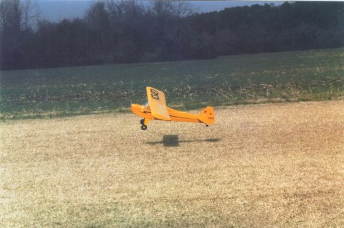
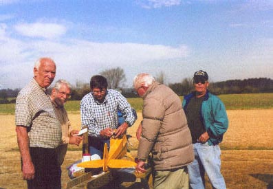 They say a picture is worth a thousand words and I think the above picture proves that to be true. It has always been amazing to me how RC modelers will help other club members when they need it. I remember when I first started in the hobby and all the guys that pitched in and helped me get in the air. No beginner comes into the hobby knowing exactly what to do and how to do it. They learn by reading hobby material, but mostly by watching and talking with other modelers. Our club can only exist if we pass on our experience to newcomers. In the above photo a group of members are seen helping Dan Freeman, on the left, to get his J-3 Cub in the air. To the right of Dan are Jack, Buddy, Gene and Loren. The group got all the details worked out and Dan was in the air. The photo below shows the Cub making a beautiful approach.
 |
|||||||||||||||||||||
Lucky
By Wayne Long
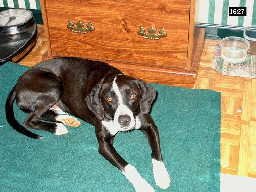
This is Lucky. What does he have to do with aircraft you might ask? Well I was on my way to go flying when I discovered him on the side of the interstate. That's what! He was skin and bones and about to get ran over by a truck or car. I rescued him and brought him home and fattened him up a little. He is still a little skinny but has a nice coat and is coming along fine. We call him Lucky because he is lucky to be alive and to have a new home. I suspect he was dumped by some uncaring person. I don't see how some people can have so little respect for life even if it is animal life. He too is one of God's creations. Please, be kind to animals.
 |
|||||||||||||||||||||
I had a problem with the pushrods in my LT40 ARF. I bought this kit last winter from Hobby Haven in Des Monies while I was still living in Grinnell. I flew it there several times back in the winter and spring and was very happy with the airplane. I sent you some pictures of it at that time taken at the old municipal airport in Grinnell. I have since moved to New Port Ritchie Fl. When I got my plane here I took it out to a local flying field to fly. I set the airplane up and preflighted it carefully with a member of the local club and everything was found to be OK. The airplane than set in the 90 degree sun for over an hour before I flew it. When I took off I found that I needed all of my down trim to stay level and when I made my first turn after climb out I noticed that I had only very little elevator response. I managed to make my left turn but lost considerable altitude in doing so. I knew something was wrong so I regained altitude going back across the field to set up for another left turn and landing. At this time it was almost impossible to control because of almost no ele. response at all and the airplane spun into the ground. The fuse is damaged almost beyond repair and the wing and tail where also severely damaged. However the engine does not appear to be hurt. Upon close inspection of the wreck it was found that the pushrods had become very soft and pliable. The pushrods where still connected but I could push the elevator down with almost no resistance at all. The servo tray had broken out of the fuse but I was still able to hold it in place while pushing down on the elevator and the pushrod just bent. I had used a full piece of the music wire that was provided in the kit that is threaded on one end and had inserted the music wire down the pushrod on assembly with the clevis attached on the exposed threaded ends. This was done at both ends of the pushrod. The flex in the rod was coming from the unsupported area between the bulkhead at the rear of the radio compartment and the bulkhead at the front edge of the horizontal stab. The outer pushrod was securely glued at both of those bulkheads. The distance between these bulkheads is about 15 inches. That seems (to me) to be too great of a distance for unsupported pushrods. But being a fully covered ARF I chose not to cut open the bottom of the kit to add more supports to the pushrods when I built it. I also was so impress with this kit at the time that I was building it that I took the attitude that "if SIG designed it this way, it must work". And it did not seem to be a problem until I got to Fl. in this heat. Let me also include in this note some of the changes I made to this kit. I removed most of the dihedral, leaving only about 1 in total and glassed about 2 inches of the wing mid section and mounted the wing with nylon wing bolts. I was more interested in a sport type plane instead of a trainer. I installed a landing gear block and the main gear and the complete tail wheel assembly and operating hardware from a LT25 to make it a tail dragger. Mostly because I don't like nose wheels. Power was from a Saito 56-4 stroke. I was very happy with the way this plane flew, not quite a trainer but more of a very forgiving sport plane. Needless to say I was very happy with it. I thought you might be interested in hearing about my problems with the pushrods and I would be interested in knowing if you have heard of this problem from anyone else. Well anyway I am not discouraged and I will build another one and make the same mods on my next one, but on the next one I will cut the bottom of the fuse open and add more supports to the pushrods. Thanks for listening to my problem.
Somewhere in central Florida
Reply From Sig
Dear xxxx,
Sorry to hear about your problem with the LT-40 pushrods. The pushrods are made of nylon, and I know that they will expand in length when subjected to higher humidity, and likewise they will shrink if the humidity drops. That's why nylon pushrods are almost never used by pattern fliers or other competition flyers, they can't stand the trim changes that nylon pushrods cause. In most cases, the tendency for nylon pushrods to change length with the weather is not a problem for the average sport flier. Evidently it is for an airplane that was assembled in "dry" Iowa and taken to "humid" Florida. I really believe that is the root of the problem you had. It should be enough to anchor each end of the nylon tube, as the kit instructs. It's just like the cable controls on a motor cycle - they are only anchored on each end.
I hope you have better luck with the next one.
Good flying,
Kadet LT-40 Designer
The kind of worthless drivel that some companies try to pass off as customer service never ceases to amaze me, but this one is a classic!
|
|||||||||||||||||||||
Part One
By James Goss
If you like to build models like I do then you probably have an area around your house designated as your workshop. This could be an unused room in your house such as a bedroom, dining room, garage, basement or an exterior building outside your home. Wherever you have your building area located I am sure you spend a lot of time there like I do. When it comes to shop safety we have to really be careful in our line of work because of the type work we are doing. Trying to build tiny little parts like we are involved with can actually be just as dangerous as fabricating large industrial devices. This may sound odd to you but I have personally seen several bad accidents take place. These accidents were a result of someone trying to fabricate a tiny little part from wood while operating large woodworking machinery. Fingers severed because tiny parts require that you hold them close to the saw while cutting to shape. I have seen table saws propel small sharp pieces of wood that got pinched between the saw blade and fence, across the room like a bullet. Breaking windows and hitting bystanders, these projectiles could be deadly. There are ways to prevent these accidents from happening and I feel it is good to talk about them from time to time so we will stay on our guard. If you have ever had an accident around your shop or have seen one take place or have simply heard about one, send in the details to me and we will talk about it in the newsletter.
What I would like to talk about today deals with electrical safety around the shop. I can guarantee you that the number one electrical safety problem around most shops will be related to electrical grounding first and then improper equipment being used, in place of what is called for, as a second most serious hazard. The theory of grounding is not hard to understand and is probably the most misunderstood part of any electrical installation. If you have two objects that have the same electrical potential on them it is safe to say that there will be no current flow between them. This is what equipment grounding does; it prevents the chassis of a device, such as a metal power tool, from becoming electrically hot if a fault occurs in that tool. If the metal chassis of a tool you are using becomes hot, because of a fault in the electric motor, and you are standing on a floor that is an electrical conductor, such as damp concrete, your body will be exposed to 120 volts ac. The actual amount of voltage will depend on how good of a ground you make contact with. 120 volts ac is a lethal voltage! More people are killed each year with 120 volts ac than any other voltage.
If you are holding the faulty hand tool and touch another metal case tool that is earth grounded you will receive the full 120 volts and could easily be electrocuted. One side of the ac line is earth grounded and is called the neutral conductor. It is also referred to as the grounded conductor. This is where the confusion comes in; the grounded conductor is not the grounding conductor. The grounding conductor (ing), also called the equipment ground, is the bare or green conductor in a cable or conduit. It connects to the metal chassis of tools and appliances so that if a fault does occur in that piece of equipment and a hot wire touches the chassis, a short circuit will occur and a breaker will trip. The idea here is that it is better to shut off the branch circuit than to have a hot chassis just waiting for someone to touch it and get electrocuted. So let me say again that if a fault occurs in an appliance or hand tool and the hot wire touches the chassis or frame, the branch breaker will trip only if the frame of the device is earth grounded. If the frame is not grounded it is said to be floating and can carry the full potential of the hot wire. There is nothing more dangerous than to have a hot chassis on an appliance of hand tool in an environment where there is a lot of other grounded devices nearby. Over the years I have checked hundreds of electrical systems that had improper grounds throughout the building. A large portion of these cases were brought to my attention because someone was receiving and electrical shock and wanted me to find out why.
The receptacles in your home or shop are required to be of the equipment grounding type. That is to say that the receptacles are a three wire two pole device. If your receptacles are in a metal box, and older systems will be, then the box must also be grounded as well as the receptacle. It is not by code standards to ground the box only and depend on the screws that hold the receptacle in the box to bring a ground from the box to the receptacle. The reason for this requirement is that if the screws become loose the receptacle would not have a solid ground. Even though this is a code violation you will find this still being done. If the receptacle has a self grounding strap that holds one of the two 6-32 screws, then it is excepted, of if you have metal to metal contact between the receptacle and metal box then it is also excepted, but this is rarely the case. The best way is to have the grounding wire bonded to the box and also bonded to the receptacle ground terminal.
To check your receptacle for proper grounding is simple. Have someone that is experienced with measuring ac voltage to make these simple tests. Set the voltmeter for ac voltage and select a range that will be equal to or higher than the 120 volts. The face of your receptacle has two vertical slots and one half circle. One of the slots will be longer than the other slot and this is the neutral slot. The shorter slot is the hot side of the receptacle. The half round circle is the ground prong. Place the meter probe into the hot slot and the other probe into the ground prong. If the receptacle is grounded properly the meter will read 120 volts. Next place the meter probes between the neutral slot and the ground prong; the meter should read zero volts and not 120 volts. If you read zero on the first test and 120 volts on the second test, the receptacle is wired backwards. That is to say that the hot and neutral conductors are crossed. This can be a very dangerous situation and needs to be corrected as soon as possible.
You may wonder what is wrong with having a receptacle wired backwards, the neutral and hot wire reversed. It is true that the device you are operating with the receptacle will still function, but this can bring on many types of accidents around the home and workshop. For example lets take a simple floor or table lamp. The lamp socket has two wires connecting to it. The hot wire goes to the center terminal in the base of the socket and the neutral goes to the screw shell. With this connection it will be relative safe to change a light bulb if the lamp's switch is on. Of course the switch should be off, but with a blown bulb the switch may have gotten left on by mistake, this is very common. So when you start removing the bulb from its socket the threads will be exposed after a few turns of the bulb. You can actually touch the threads on the screw shell of the lamp while it is still making contact to the socket. This will be ok because the screw shell of the socket is connected to the neutral, which is grounded.
You can see that if the two wires were reversed in the receptacle where the lamp is connected, the screw shell will be hot instead of being grounded. Now when you touch the exposed threads on the base of the lamp you may receive an electrical shock. This will depend on how well of a ground you are standing on or if you are touching another grounded object in proximity to the lamp. Having the hot and neutral wires reversed in a receptacle is dangerous. This is only one example of what can happen, but there are many accidents that can be caused by incorrect wiring of a receptacle.
120 volts is a nominal voltage rating and your home or shop may vary from this value. It should be in the range of 110 to 125 volts, this is not that critical. You can buy a small receptacle tester for about $5 at Lowes that you can plug into the receptacle and it checks all three voltages at the same time, neutral to hot, hot to ground, and neutral to ground, by having three combinations of lights to be on or off as an indicator. This little device is well worth the money and it allows you to test your receptacles fast and easy. You should at least check your receptacles two times a year to spot a hazard before it happens.
It is unexpected electrical faults that claim the lives of hundreds of people each year. The electrical system in your home or shop requires regular maintenance because it is under constant use and demand. The simple day-to-day routine of plugging and unplugging a device into a receptacle creates ware on the electrical connections and mechanical movement of the receptacle. This tiny movement will in time cause the screws and wires to work loose and loose connections create voltage drop and voltage drop will produce heat. So maintenance is important, but having the system installed by National Electrical Code standards is a must if you want to be assured a safe electrical system.
Next newsletter in Shop Safety Part Two, I would like to discuss GFCI protection and also some good facts and tips about using extension cords in your shop. Remember, when installing an electrical system to first make it safe and then make it work. It is easy to wire up some lights and receptacles and get the lights to come on when you flip the switch and have the receptacles furnish 120 volts, but it requires a little more effort to make it safe when faults occur in the system.
|
|||||||||||||||||||||
Flying- SOMEWHERE ELSE!
-by Clay Ramskill
Our flying field is certainly not the worst to be found in the area - its not the best, either. We fly there because we like the field, we like the people, its comfortable to us. But sometime, we're probably going to fly at other fields. Perhaps the easiest, most painless way to do this is by invitation from a member of another club. Whenever possible to accept such an invitation, do so. You will enjoy the experience of meeting other people, seeing how they do things, seeing their aircraft and so on. And you will get the experience of flying from a different locale; this is not as easy as it seems! The different surroundings, the lack of the usual visual cues you're using (whether you know it or not) and unfamiliar people and aircraft types surrounding you puts a heavy load on your nervous and sensory systems. If you're there by invitation with a friend it really helps. The worst case scenario is when you've moved to a new city - you may have made a phone call or two, but you basically arrive at some club's field as a total unknown, and essentially end up "showing your stuff" to the watchful eyes of numerous clubmembers who are in the process of evaluating you, as you are them. NOT a relaxing situation! And in between these two extremes are a number of interesting and pleasurable ways to fly from another field. You see the "advertisements", flyers posted at hobby shops, or in Model Aviation, for various events:
Open House- A club just opens their field for others to come watch or fly; you do need to check and see which is the case unless its obvious from their flyer. This is a pretty stressless way to fly from another field and meet some other flyers.
Fly-in- More common than open houses, and usually more structured, these are meant to get other flyers in to fly and socialize, and are also money-makers for the host club. A landing fee is generally charged, there will usually be a frequency impound, aircraft inspection, a rules brief, and so on to ensure safety. There may also be raffles of neat equipment, good food for sale, a vote for best plane in various categories with prizes, perhaps other pilot prize drawings, and maybe some neat flying demos. Generally there is no competitive flying at a fly-in.
Fun Flys: These can range anywhere from guys doing crazy events with their sport planes just for the fun of it or for a ribbon, all the way to dog-eat-dog competition with specialized aircraft. This is another situation where it would be a good idea to make sure of just what you're getting into! Our idea of a fun fly, and the "sorta" competition we do, may be a long way from some other clubs concept, where its an actual compettive event.
Competitive Events- These are highly structured, usually adhering to AMA rules and guidelines for the events. Promotions will indicate the numbered AMA competitive events to be flown; the AMA rules indicate the type of plane and all the particulars of how the competition is run. These AMA class events cover the whole range of modelling - from racing, to combat, pattern to rubber powered free flight. You should be very familiar to the AMA procedures involved before even thinking about entering such contests. Those who do find them stimulating and fun. Regardless of the type of function you're going to attend, be sure to look very carefully at the literature advertising it. Many functions have limitations, depending on what the Host club is into and what they're capable of handling. For instance, they may require IMAA legal planes - these are large planes, covered by IMAA rules. Restrictions may be for warbirds only, or for WW2 warbirds only. Or 4-strokes only.Or AMA #301 events only. Or whatever! Nearly all the ads will give a POC - a point of contact. It would be wise to give the contact person a call to make sure you know what you are getting into before you drive all the way to East Somewhere. And make sure you have GOOD directions to the field involved. Don't settle for "just follow the signs from downtown"!
A few pointers for going to ANY other field to fly. HAVE your AMA card (not a copy); you probably won't fly without it. Any AMA sanctioned event requires that your radio be "1991 certified". Expect that your plane and perhaps the radio will receive a thorough safety check. Be sure your plane has your name and number on or within, an AMA requirement. Have the appropriate frequency number and red streamer, as well as your name, on your transmitter. On arrival, get familiar with the frequency control system in use. Be sure that you receive a briefing on any peculiar field rules - it's amazing how often you find out about these AFTER you've unwittingly broken them! Be sure you're aware of field and/or event requirements; sometimes a "spotter" (someone who stands beside you and tells you when you're about to hit another plane!) is required for each flight. Maybe there is no taxiing allowed at the field or for the event. Sometimes you're only allowed to start engines out at the runway; ie no running engines in the pits. Some clubs may have a time limit for how long you can fly, or how long you can hold on to a frequency pin.
Be sure to take necessary items with you - the host club may not provide chairs, your favorite beverage, or shelter for you or your plane. You should certainly have a few bucks with you - for landing fees, to enter a raffle, or to buy something neat that's for sale. And if at all possible, take a friend. That way you have someone to talk to, you can trade "spotting" duties, etc., and perhaps ease each other's apprehensions about flying in front of a bunch of strangers! But by all means, when you see a good opportunity to fly at a different facility, do so. You will be treating yourself to a taste of the wonderful combination of diversity and cohesiveness that make our hobby such an interesting pastime
|
|||||||||||||||||||||
By James Goss
This is something new to our hobby and will probably catch on for the larger planes first and then the smaller ones as well. What we are talking about here is having a servo connected to the receiver, but without any direct connected electrical wiring between them. Instead of having copper wire connecting the servo to the receiver, fiber optic cable will be used. With fiber optic cable being used to transfer data between the receiver and servo there is no electrical current flow. It is current flow that causes all the glitch problems we face in our hobby. Current flow through a wire generates a magnetic field that starts at the center of the wire and expands out around the wire depending on how strong the flow of current is. This magnetic field can be picked up by other wires in the form of an induced voltage and create an unwanted glitch. The servo wires can also receive an induced voltage as well as generate one. This actually happens with all servo systems no matter how long the wires are, but on a small scale, and you do not notice the tiny glitches.
When the wires get around three feet in length or larger, the induced voltages may begin to be really noticeable in the form of glitches. Three feet because our frequency is 72 mhz and at that frequency the wavelength is 4.1 meters long. Our antenna system is based on a ¼ wavelength and three feet is in that range. In other words ¼ of 4.1 meters is almost 1 meter and 1 meter is 39.37 inches. So this is why the three-foot rule applies here. With extremely long wires the servo may become so erratic that you can't use it at all.
By using fiber optic servo extensions the length becomes immaterial and the servo can be placed at any distance you desire from the receiver. If you have three servos on each aileron you still only need one fiber cable going to each group of three. Remember that light pulses are transmitting the servo data. We will come out of the receiver as always with a standard servo wire. This wire will go to the optic transmitter, which changes the electrical data pulses into burst of light. This transmitter will be located near the receiver and is very tiny in size. The fiber optic cable will leave this transmitter and can be any length you desire to reach the servo area. At the servo location you will have a tiny optic decoder that decodes the encoded light pulses and converts the servo signal back to electrical pulses. The servos must have electrical pulses to operate, remember that the light pulses do not reach the servo. At each servo location you will also have a servo battery pack to drive the servos. In a regular servo installation the three wires going to the servo carries the servo dc power on two wires and the third wire is the servo signal wire. So in the fiber extension system we are eliminating the signal wire and having a devoted battery for each extended servo area. These batteries can be much smaller in size because they only supply a fraction of the total servo current. This also provides more failsafe for our planes because if one of the batteries goes out on one of the ailerons, or elevators, we still have the other half still in operation for landing our plane.
You can see that in large giant scale planes there is going to be a demand for these fiber optic extension systems and in the future I think we will find them in use as part of out regular equipment on small planes as well. At this time the optic extensions are selling for around $65. I am sure they will fall in price as they become popular. You may wonder why there is not a system that will allow us to still use one battery for all the servos and use the fiber optic line for the signal wire. The problem we have with a design such as this will be that as the dc lines carry the power to the servo they are acceptable to generating and receiving induced voltages as mentioned above. Even though these lines do not go directly into the input of the servo, as does the signal line, any amplitude changes on these power lines will be picked up in the amplifiers in the servo and treated the same as a incoming signal. Even with voltage regulators found at the input of the servo these glitches will still get through because the regulators can't react fast enough to keep them out of the amplifiers.
|
|||||||||||||||||||||
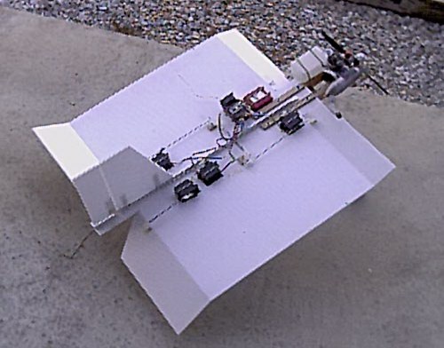
By James Goss
You have probably seen my Stamp with twin rudders. I was very pleased with the way it handled in the air and on the ground. It also had a unique look in the air and was no more difficult to fly than the regular Postage Stamp. On the way home from the flying field the other day I was thinking that if the Stamp flies so well with twin in-line rudders, how would it do with twin elevons? In other words have a set of elevons in the rear of the plane like they are now, and also have a set of elevons located at the front of the plane. The elevons at the rear of the Stamp are 4-inches wide, I think the front elevons would probably need to be a little smaller, about 2.5 inches and have less throw than the rear elevons. The Stamp already has the tightest loop of any plane; it is more of a tumble than a loop. Of course it will also do nice big loops like any other plane, but with front elevons there is no telling what it will do. When I got home from the field I went to work.
I already had some Stamp blanks cutout so I made another aluminum spine and attached the fin and rudder. This time I decided to try a new type spine. Instead of using aluminum channel I thought I would try a piece of ½ inch aluminum angle. The ¼-inch channel weighs about ¾ ounce less than the ½-inch channel I have been using. The ½-inch angle aluminum saves another ¾ ounce and I think it still has enough strength. In about two hours time I had the basic Stamp ready to assemble. I had thought about the twin elevons, but I hadn't thought about how to hook up the control surfaces.
First I had to get oriented on how the two sets of elevons needed to move in respect to each other. One set of elevons is confusing at times and two sets can really get you to thinking. I started with the elevators first and finally determined that if the rear elevator moves up, the front elevator on the same side also needs to move up. This would push the rear of the plane down while lifting the front of the plane. So the elevators would be simple to gang together. I could simply connect the bottom of the rear elevator (I would use back-to-back control horns on the elevator) to the top of the front elevator by routing the pushrod through the center of the wing. If the rear elevator moves up, the horn on its bottom side will pull on the front elevator horn that is mounted on the top side of the front elevator and they will both be moving up at the same time. Likewise they will both move down at the same time. This looked good on paper so I build the control linkages and ganged the rear and front elevons together. They really worked smooth and everything on this project was well under way, or at least I thought it was.
With everything hooked up I decided to give it an aileron test. As the right front and rear aileron moved up for a right turn the left front and rear moved down and I thought everything again looked fine. After double-checking the aileron logic again I could see that this setup could not possibly work. In a right turn the right rear aileron would take the right side down like it should, but the right front aileron would try to lift instead of lowering the right side. So back to the drawing board I went and I soon had a workable scheme.
I determined the ailerons must be cross-coupled and on the same side of the wing instead of going through the wing from top to bottom. The run of the control rod was so long that I decided to use bell cranks about midway of the wing. It would require four bell cranks with two on each side of the wing mounted back to back. It worked out best to gang the right rear and the left front aileron together on top of the wing and the left rear and the right front together on the bottom of the wing. When completed everything again worked smooth and I was ready to proceed. It is strange that the elevons hookup turned out to be an x connection. From day one of the Stamp plane I have related to the kites I would fly when I was a small boy. We made them from notebook paper and used two sage straws crossed over in the center of the paper to make an x configuration. It looked like this:
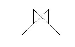 This kite is very close in appearance to my Postage Stamp plane, and I guess I owe the Stamp design to this little kite. This Twin Elevon Stamp is a great flyer and seeing all the control surfaces operate while in a close hover is really grand.
 |
|||||||||||||||||||||
By James Goss
If you could only have one major power tool in your hobby shop work area what would it be? I think it would be interesting for all the club members to know what you think is the most important power tool in your shop. Some club members may be getting ready to buy some tools for their work area and it might help them decide if they knew what is really needed by modelers in our hobby. Of course there will be many different answers to this question because people do take different approaches when it comes to doing anything. There may also be some tools that carry equal value when it comes to their importance in our shops, but I think that overall we can create a list from the most to the least important major power tools we would like to have in our shop. So send in your views to me and we will get the list underway.
Why buy tools that just set in the corner and collect dust? Over the years I have done just that, buy a tool and never really use it. When starting out in this great hobby I would have really appreciated seeing a list such as this that would give me some ideas of what tools was a must to have. We can do this for small hand tools also, but lets keep this list for the bigger power tools and do the small tools at a later date. This is a good chance for you to give some input to the newsletter and also help the members. So take a few minutes and think about your most often used power tool, then send in your choice and also why you like it. We will print the results in the next newsletter.
|
|||||||||||||||||||||
By James Goss
I have used servo tape many times over the years, but here lately I have really been using a lot of it. With my new Postage Stamp design I do not use servo wells anymore, instead I use servo tape and one nylon tie to secure the servo, battery, and receiver to the coroplast. This method is much faster than cutting servo holes and using wood rails to secure the servos. The servos are mounted on their sides to give more area for the tape to hold. I have never had a servo to come loose from the tape, as a matter of fact I have to use a putty knife and pry the servos away from the plastic when it is time to change the radio gear. If it is installed correct the servo tape will hold as well as any method I know of for securing a servo.
Here lately I have been experimenting with many different design Stamps and have found it necessary to change my radio gear in some cases two or three times a week. It is quite annoying to remove the servo tape from the servo because it will not turn loose clean; it leaves a residue that is very time consuming to remove. The only way I know to clean the servo tape from the servo is to scrape it and then use acetone and elbow grease, takes about ten minutes to clean each servo. This can add up into a lot of valuable shop time wasted if you do several radio changes each week. Also let me say that you must be careful with the amount of acetone you use on the radio gear. Do not soak the servo with acetone, instead use a tiny amount on a shop rag and rub the servo with a circle action until the residue becomes soft. You do not want to get any acetone inside the case of the servos.
I knew there had to be a better way to remove servo tape from the servos than the method I was using, and here is what I have come up with. This is the best way I have found to install servo tape to plastic or wood. First be sure to have a servo tape that will cover the entire area of the servo, usually a 1-1/2 inch tape will do this. Clean the servo with alcohol at least three times to remove any oils. Do the same for the plastic area that will accept the servo.
Here is what makes the difference and allows you to remove the servo tape from the servo in about ten seconds.
After you have cleaned the servo with alcohol and before you put the servo tape on the servo, wrap the servo with black electrical tape, about two good layers will be fine. I use Scotch 33 + because it bonds even in cold weather. It cost a little more, but it is worth it in the long run. After you have wrapped the servo with the electrical tape you must clean the tape with alcohol to remove any body grease you got on it while wrapping. Now peal the backing from one side of the servo tape and bond it to the servo. The servo is now ready to install and I assure you that the servo tape will bond to the electrical tape just as well as it will bond to the servo. When you get ready to remove the servo simply pry it off with a putty knife and cut the electrical tape to peal it off, takes about ten seconds. I have found this method to work well and will never use servo tape again without first placing electrical tape on the servo. I would not recommend using electrical tape unless you are mounting the servo on its side because placing electrical tape only on the bottom of the servo without wrapping it around the servo might not hold well enough.
|
|||||||||||||||||||||
#1
From: [email protected] (Leon H. King)
Hi, I was interested in your article on pulse code modulated transmitters.
Could you recommend a good but reasonably priced 4-channel PCM transmitter? I know of two brand names! Thanks!
Hi Leon,
I have always been a user of Futaba and have always been pleased with their performance. All brands use the same technology today and I would think one is about as good as the other. Some modelers swear by a certain brand name as being the best around, but in reality they are all well designed and will give you years of service. Good luck. James
#2
Subj: Postage Stamp
Date: 02/11/2003 12:53:29 AM Central Standard Time
From: [email protected] (ray)
HI> I just wanted to say thanks .. I really liked your web site, you did a great job explaining how to build your different planes , I just really love them, and I just got stated with coroplast, so this gives me a chance to show some of the other guys at my club the great things one can do . so thanks and keep up the good work, god I love those planes,, thanks so much. I have some 4mm coroplast in my shop now, will begin work in the morning, I'm retired and 62, so have the time to make these up, I live in Wisconsin so to darn cold to fly, but can have them ready for this spring, Thanks so much for sharing you insight and explanation of the how to..Ray
Hi Ray,
Good to hear from you up in Wisconsin. I think you will truly enjoy flying a Stamp. I know I have had more fun with these little planes than any other planes I own, and that includes giant scale. Just remember that it takes a little while to get familiar with these little planes so don't get discouraged after the first few flights. After you get a little experience with them the fun really begins when you hover around about two feet above the ground, then set it down in a vertical landing. Good luck with your retirement and the Stamp. If I can help you in any way just let me know. James
#3
Subj: Postage Stamp
Date: 02/16/2003 11:38:45 PM Central Standard Time
From: [email protected] (Steven)
James,
Hello there! I'm Steven Cheldelin and like you I've been flying for about
31 years or so. Been through the whole gambit (a few times) and the last
two years I've been flying helicopters.
Then along came that damnable square thing. I hacked one together for
something to fly during the winter, and now I'm completely addicted.
Until the last few months, I had no idea about these amazing airplanes. I
just found your website this evening and am very excited to read through it.
I have plenty of modeling experience, but as you well know, these things
have their own little quirks.
I've begun placing ads for "Short kits" on ebay for $6.95 each. I hope to
provide hundreds of modelers access to these fantastic airplanes (and keep a
nice pile of coroplast at hand to support my habit). I'm worried about
using the name "Pizza Box Flyer" or "Postage Stamp" because I am not the
originator of these names and had nothing to do with their development. I
would like to give credit to yourself and the others who made them up, but
if I refer to you or your websites directly, it may cause an undesirable
increase in traffic and a flurry of questions.
Would you be opposed to a kit called the "Postage Stamp Flyer" as long as
proper credit to yourself and a reference to your website was included in
the advertisement?
I have the resources at hand to create a new website for the sole purpose of
providing instruction and answer questions, if needed. I'm still not
comfortable using your name. How about the Square Flyer? I just don't
know....
I appreciate your help with this.
Thank you,
Steven Cheldelin
www.rcflyer.net
AMA 588516
LSF 1007
Hello Steven,
I would be honored for you to use the name Postage Stamp on your kit. More than anything I wanted all modelers to know about these great little planes and how much fun they are. Any method that spreads this information is more than fine with me. If I can help you in any way please let me know and if you get a site going I would like to be your first visitor. James
#4
Subj: Hello
Date: 02/18/2003 3:18:57 AM Central Standard Time
From: [email protected] (stompanatto Mcvinia)
Dear sir,
My name is Dumitru and I am from Romania.
I want to build an R/C transmitter and receiver for my boat model. I look for plans for what I want to do but I don't find. If you can help me, please send me an e-mail. Thanks.
Hello Dumitru,
Good to hear from you in Romania. In order to be of some assistance to you I will need a little more information about your hobby in Romania. First of all what radio frequencies are allocated for your hobby in Romania? Second, do you know the maximum power allowed for the transmitter? Third, do you know what bandwidth is used? Here in the states a transmitter can only be built and tested by qualified persons that hold an FCC license to do so. It is a federal law violation if anyone adjusts the frequency of a transmitter and does not hold the correct certification to do so. Do you have a similar law in Romania? This is why very few RC transmitters are home built today in the states. I do have an FCC license that allows me to adjust and build transmitters, but nobody in the stated does that because it is much cheaper to simply buy a manufactured transmitter and receiver. Also it is expensive to obtain the proper equipment for alignment of the transmitters so they will be on the correct frequency. The only person that would take the time and effort to build such a system would be an RC hobbyist, which is also an electronic hobbyist and has an FCC license, and is doing it for the gratification of the hobby and not to save money. He will pay several times the cost of a manufactured system and it probably will not look as nice and operate as well. The physical size will also be larger because a home hobbyist can't operate on a micro scale as the manufacture can.
As you have found in your search for plans to build such a system, there is no demand for home built systems anymore. Do you have access to the manufactured systems in your country? If so I would recommend that you go with one of these to save a lot of time and money. If you do not have access to a manufactured system and still would like to build your own homemade system, I may be able to help you with your project. James
|
|||||||||||||||||||||
What are the Differences Between a Postage Stamp and a Pizza Box flyer?
By James Goss
You may recall that I started flying my Postage Stamp plane in February of last year, 2002. The Postage Stamp was a result of having built the Ace Of Spades, a flat plane with a fuselage. The Ace flew well and I decided to share this design with other modelers so I posted it on the internet. This post got some modelers thinking about the same design as I, a flat plane with no fuselage, just a wing. Two flat designs came out at about the same time. I called mine the Postage Stamp and Dave McDonald named his a PBF (Pizza Box Flyer). Dave lives in Missouri and is a really nice guy that loves to help other modelers. We both tried many different size planes and determined the 24-inch square design was the best, so that is what we both went with. Other than having the same size wing there are several differences between the Stamp and the PBF that make them each unique.
The first major difference is that I designed the Stamp with landing gear whereas the PBF has no gear. Being able to land and take off really adds to the fun of the Stamp. There is nothing more pleasing to watch than a Stamp doing a vertical landing and immediately taking off again. The PBF was designed to be hand launched and is lighter in weight so it is really active in the air. The Stamp's landing gear are long and slender so they will absorb the shock of set down and prevent the prop from hitting the ground. Sometimes the gear appears to be walking across the ground during takeoff, this is hilarious. Even though the gear looks long a frail, they are very rugged and will survive many crashes. I have never had the gear to break on any of my Stamps, but I have heard of one from a club member that did break. So the record for the landing gear is good and I don't see why the PBF guys don't use them.
The next difference between my plane and Dave's plane is in the placement of the engine. Dave placed his at the leading edge of the wing; I placed mine forward of the wing. Placing the engine at the wing's edge will require the servos to be mounted close to the front of the wing to achieve balance. This requires long push rods to connect the servo to the elevons and rudder. Mounting the engine out front allows the servos to be installed at the rear of the wing with short push rods that produce less flexing of the rods. Having the engine at the leading edge appears to give the plane more ability for quicker turns and darts, another reason why Dave's design is so quick in the air. We chose the same mounting style for the engine, using two wood rails. I use maple for these rails and have never had one to break at this time.
The third difference, and this is a major difference, is the vertical stabilizer. The PBF's use a tiny fin and rudder, the Stamp has a relative huge fin and rudder. The Stamp needs the larger fin and rudder for good ground handling. In the air the Stamp has good rudder control and will do a great flat spin. The Stamp will exit a flat spin instantly, when you return the controls to neutral, and fly away with ease. The BPF's will not recover from a flat spin with the same ease, as the Stamp will. When you let the sticks go, the plane continues to spin; you have to work to get it to recover. So this larger fin and rudder does make a difference.
It is interesting how the two planes, as different as they are, came to be and how fast they have spread across the country, and the world for that matter. By use of the Internet, in less than one year, these planes are showing up at flying fields all over and are spreading like wildfire. I knew from day one that these planes would catch on because of two things; they are dirt cheap to build and they fly well. This combination can't fail and not to mention they are almost indestructible.
So even though Dave and I built two planes that are similar in design, as you can see they are two different planes. Dave's design, the PBF, is leaning toward a lighter, faster, quick turn, hand launch and dead stick landing type of plane. My design, the Postage Stamp, is for very slow flight and control with takeoff and landing capability. By and large, they are both good flying planes and I think the sky will be full of the little planes this time next year.
|
|||||||||||||||||||||
The 2003 mall show went well this year. I will report on it next edition because I am still waiting on pictures.
|
|||||||||||||||||||||
RC and the WEB
by Clay Ramskill
Meet Rich and Mary. They live in the Northwestern U.S., are members of a thriving RC club; he's the Secretary, she does a really nice newsletter. They're both nice folks who write well, have a menagerie of critters around their home (including a small herd of Llamas), and enjoy RC people and flying.
As much as I'd like to, I've never met Rich or Mary. I've never even talked to them. But I've gotten their newsletter, transmitted to me in full color in just a couple of minutes. I've corresponded with them, exchanged some files -- all through my computer.
On the World Wide Web portion of the Internet, modeling, individuals, clubs, and national organizations (like the AMA) have an ever-increasing presence. From Iceland to Australia, modelers share pictures, information, and experience to whoever may seek it out. You can order parts for your plane or engine. You can send and receive electronic messages (E-mail) in a flash to any similarly equipped computer. You can get the specifics of Dr. Selig's latest low speed airfoil research, or download (retrieve to your computer) other aerodynamic information. You can read magazines. You can find RC flying sites in any state, or find information on RC clubs. You can find out how to tune your engine. And most of everything you do find is only the tip of a very huge iceberg! All you need is a computer with a modem (connects your computer to your phone line), access to the internet, and software to make it all work (a browser). The advice of someone who's already "there" is a good idea, too.
The internet is arranged in several formats; the easiest to use and the most rapidly growing portion is the World Wide Web (www). Under this protocol, text, pictures and other data can be sent worldwide, as quickly as calling across town. Hundreds of thousands of individuals, companies and organizations host "home pages", which may only be a samll amount of information or be the front for an extensive collection of goodies. And any picture or word can be highlighted as a "link" - if you click on it, you are transported to another site, which could be anywhere in the world! You see the "addresses" for these sites increasingly in your paper, magazines, on the TV, even billboards as folks jump onto the information superhighway.
The AMA "page" (http://www.modelaircraft.org/ )is a good starting point -- they give you staff diectories, contest schedules, lots of stuff you can download to your computer (like an application to join the AMA), and lots of "links" to other WWW sites all over the world. Tower Hobbies (http://www.towerhobbies.com/) and Hobby Shack have even more extensive sites, including club listings and full catalog and ordering capability -- plus, even more links to other sites.
Many RC clubs also maintain their own WWW pages. Typically, they will include information about their club, perhaps a map to the flying field, several editions of their newsletter, and pictures of their field and members' models. Some clubs even have two newsletter editors -- one for "snail mail" and one to do the WWW edition. Clubs will also include links to other clubs and related organizations, like their local city Chamber of Commerce.
Individuals also sometimes host RC related WWW pages. These range in complexity from a few pictures of a guy and his RC model, to extensive compilations of information, pictures, or trivia. And, as always, more links to other sites!
Online Services" such as CompuServe, Prodigy, and America Online also have areas for modelers. In CompuServe, it is called ModelNet, and it includes archive pictures, data, and "chat groups" where folks can trade BS with each other. (Some of these guys need to get a life!) Usenet, another area of the Internet, is also a "trade stories" type of operation. I've "visited" RC sites all over the world, not to mention the U.S. The logos shown are from Norway, Cyprus, Australia, and Belgium -- only a few of the myriad of clubs and organizations with a WWW presence. If you have the time to poke ("surf") around on the WWW, I highly recommend it. Just don't let it detract from your building and flying time!
|