Cow Patty News
Monthly Newsletter
April 2002
The Anniston RC Flyers

God Bless Amereica
What is in the newsletter this month?
|
Radio Confusion
By James Goss
This article is not in reference to the technical facet of our RC radios like you might expect it to be. Instead it is dealing with radios found around my house and how they confuse my wife Mary. I keep Mary confused about radios all the time because I have so many different radios at my house just like you do I am sure. Now I am not just talking about RC radios, heaven knows I have enough of them, but I am talking about other devices that I also call radios. Of course we have regular radios also such as AM and FM and we both refer to them as radios. Here is what really gets Mary confused; we have a remote (cordless) telephone that we carry around the house that I also refer to as a radio instead of as a telephone. In reality it is indeed a radio transmitter and receiver so I can't help but call it a radio. Being in electronics over the years I guess I tend to think on the technical side of everything anyway. Mary tells me that a normal person would call it a telephone instead of a radio. Here is another example, we now have cell phones in our home and of course I refer to them as radios also. When I start to go somewhere I will say Mary would you hand me the radio, and of course she says which one do you want? She will then say, Why didn't you say the cell phone. To make things even more confusing for Mary we now have the little Cobra hand held two-way transceivers that we use to stay in touch with each other when I am at the shop working. Naturally I call these radios a radio and this really adds to the confusion. So don't be surprised if one day I open my radio case at the field and you see a telephone in it instead of my RC radio that I ask Mary to load up for me.
|
The Old TRCC Shed Comes Down
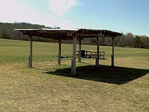
The TRCC shed has been a benchmark at our Munford field for about 30 years or more and has endured heavy winds, rain, and storms of all descriptions. The photo below shows the last known existence of the shed, about fifteen minutes before it came down. As you can see I don't think the shed would have lasted thirty more years without falling to the ground on its own. Maybe thirty more days would describe its condition better because even the termites was passing it up, so you know it was really in bad shape.
There is no telling how many people this shed has sheltered over the years. This little shed was worth its weight in gold on a hot summer day when you really needed to get out of the sun. I know I have spent hundreds of hours under this shed and loved every minute of it. The shed was also noted for the serious conversations that took place within its borders. There has been no telling how many problems solved while under the shed's comfort. Problems such as government, health, financial, space, education, transportation, sex, construction, food preparation, housing, military, and yes even rc problems just to mention a few. In a way we will all miss our little shed, but it is time to move on and put its memories behind us.
A new shed is on its way as I write these words. It will be an 18 x 20 foot metal shed and I hate to say it, but it will look a thousand times better than our old swayback shed. I just hope it to will last for thirty years and we solve as many problems under its shadows as we did with the old one. The new shed will also be easy to physically move in the future when we acquire the field that borders us and we redesign our flying site.
 |
|
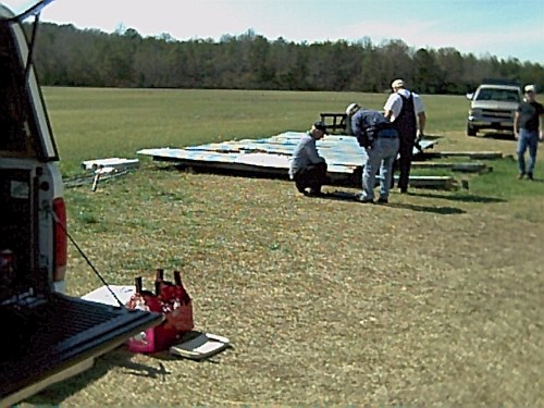
Here you can see some of the workers on the project. From left to right we have Richard, Loren, Cecil, and Jack. I took this photo Thursday at 1 pm on Feb 21, 2002.
 |
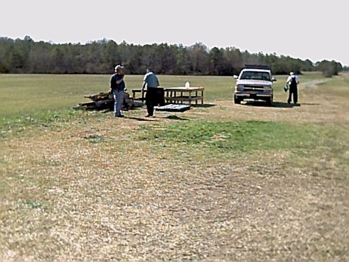
Here the TRCC shed is reduced to a nice little stack for Buddy to haul off.
 |
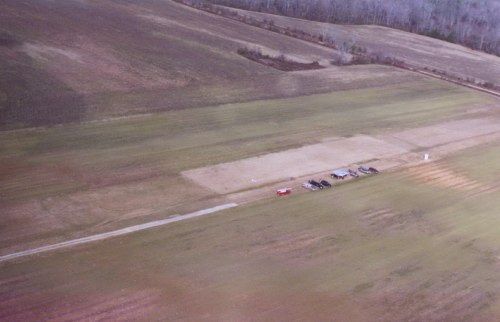
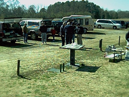
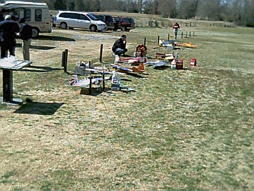
TRCC Flying Field at Munford
Photo byGeorge Langham
Feb. 18, 2002
 |
How to Build a Disk Plane
By James Goss
If you have never seen a disk plane it is basically a plane with a round wing and may or may not have a fuselage. The one I built has a fuselage that is 36 inches long and the wing is 32 inches in diameter. The wing could also be square and have about the same flight performance as the round wing. I am going to build a square wing soon, but I am building another disk plane at this time so it will be a while. Of course I could build a square wing to fit the same fuselage as the disk plane and simply change them out at the field. That would probably be the best approach because the fuselage takes longer to build than does the wing. The disk plane has some characteristics of is own and will do maneuvers other planes can't attempt. The disk I have will tail slide better than any other plane I have ever seen. It will do a vertical landing from 50 feet high and set down with the engine still running most of the time. It will go into a flat spin easier than my other fun fly planes and is truly a flat spin with its fuselage level to the ground. It will also do a pirouette with its nose pointed up and will do many of them before it drops out. Here is why I like these disk planes so much.
Building a disk plane is easy and here are some instructions that will guide you through the building phase without the need for plans. A plane of this type is known as a SPAD (Simple Plastic Airplane Design) because it is build 100% from plastic. This plastic is known as Coroplast and is used by graphic design shops to make signs like you see for campaign and other advertising along the side of the roads. It is 4 mm thick and comes in many colors with its common size being a 4 ft x 8 ft sheet. It is very easy to cut with a straight edge and hobby knife. It is relative light in weight and weighs about 3 ounces per square foot.
Gluing coroplast has been a big topic on the Internet lately and there are several ways to achieve a good bond. One method is referred to as flashing and requires the use of a torch to heat the plastic and burn off the mill oil that is left on its surface during manufacturing. This takes a little practice sweeping the torch past the plastic without burning or melting it. Once the oil has been removed you can use ca glue to bond the plastic together. Do not use too much glue; this is the number one mistake in gluing coroplast. Only place a small drop about every quarter inch. I have tried this method and prefer not to use it. Instead I prefer to clean the area to be glued with alcohol by applying it and letting dry. Do this at least three times and that will remove any latent oils. After the alcohol bath sand the area to be glued with some 150-grit paper to rough it up good. Wash with alcohol one more time and it will be ready for the ca glue. If you are gluing in formers in the fuselage, go back after the ca has cured and apply a thin coating of epoxy over the ca joints. This method has worked well for me and this is what I am now using. Another method, especially when gluing coroplast to coroplast, is to use contact cement after the same cleaning process above has been performed.
Here are the building instructions. The wing is a 32-inch diameter with elevons at the rear that measure 19-inches across. The corrugations of the wing will run at right angles to the fuselage. The elevons are hinged 5-inches forward of the trailing edge of the wing. To make the hinge surface simply remove the bottom side of the corrugation closest to the five-inch measurement from the rear. Use your hobby knife to carefully remove the bottom corrugation. The topside of the corrugation will serve as the hinge. This method also assures that you will have a 100% sealed control surface. The elevons need about 3-inches of movement both ways. Anywhere a screw goes through the coroplast you will need to install strips of hardwood in the corrugations (cells) to prevent crushing the cells. I use 1/8-inch x 3/32 light ply. It takes a lot of time to rip these so I purchased some basswood strips from Balsa USA and it really does speed up the construction. When you cut the servo hole for the rudder servo located just in front of the vertical fin, you can add these strips at that time. For the wing hold down 10/32 nylon screws you can cut some four-inch strips and insert them from the outer edge of the wing and push them into place with a small piece of music rod. When they are in place you can allow some thin ca to run down the cells to secure the strips. The wing has hold down screws at three locations. The leading edge of the wing starts at 4-inches from the front of the fuselage. The first set of wing screws are located 6-inches from the front of the fuselage. The second set are located 23-inches from the front of the fuselage. The third set is located 3.5-inches from the rear of the fuselage. For a washer and to help support the wing I use a 4-inch piece of 1/8-inch aluminum on top of the wing at the front two hold down screw locations. In the rear I use a 1-inch square piece, one on each side of the vertical fin.
The vertical fin measures 6.5-inches at the bottom and 3.5-inches at the top. It is 8-inches high and the rudder is 3-inches wide with a taper at the bottom to clear the tail wheel control rod. For tail wheel control simply connect a 2-56 rod from the rudder horn to the tail wheel bracket that is located just above the top rear of the fuselage. This rod will only be about 3-inches long. The fin and rudder mounts to the wing and is removed with the wing when it is taken off. You will need to use faslink connectors to connect the elevon servo push rods to their horns so they will be easy to remove when you take off the wing. The vertical fin is mounted by using two pieces of PVC cut for a 90-degree angle. For this I use a PVC gutter down spout and cut out the corners, this makes a perfect piece of 1-inch angle that is placed next to the vertical fin and runs the length of the fin. I then use six 6-32 machine screws, two through each angle bracket and the wing and two through the bracket and fin. The fin must also have tail wire to give it strength. For this I use 2-56 rod, one on each side of the fin, and use the full 12 inches of rod with a clevis on one end and a faslink on the other and secured with 4-40 screws.
The fuselage is built with a bottom and two sides. The shape of the top of the fuselage is what gives the wing its airfoil. From the bottom of the fuselage at the leading edge of the wing (which is 4-inches back of the fuselage front) the top measures 2 ¾-inches up from the bottom. At the balance point which is 8-inches from the leading edge of the wing, it measures 3 ¾-inches up from the bottom. It then tapers down to 2 ¾-inches again at 8-inches from the rear of the fuselage. From there it gradually curves up to 3 1/2-inches at the rear of the fuselage. This upward curve at the rear of the fuselage will give the plane some reflex, or up trim that most flying wings will require. When setting the elevons they will be parallel to the bottom of the fuselage when centered. Use a piece of cardboard and make a template for one of the sides based on the measurements I just gave you. Draw off the sides and bottom on a piece of coroplast with a pencil. You already have the dimensions for the sides and the bottom needs to be 3 ¼-inches outside measurements, so make the inside measurement for the bottom to be 2 ¾-inches. After the coroplast is bent it will measure 3 ¼-inches OD. To bend the coroplast you will need to etch the two bottom lines. For this I use a tool that Jim Woodard recommended, it is a screen door roller tool that you use to replace the screen by rolling the rubber edge into a recessed track. The tool works like a charm and makes a neat etch without cutting through the plastic. Don't use a pizza cutter! If your tool has two rollers on it be sure to use the one with round and smooth edges. After you get the fuselage bent to shape you will need to make four formers and a rear end cap from 1/8 light ply and a firewall from ¼ ply. I cut a 1 1/2 inch hole in the center of each former for ease of wire placement and also a weight consideration. Glue some hardwood to the formers at each of the wing bolt locations. I used 1/4 x 1/2 basswood for this on the last fuselage I built. Be sure to clean with alcohol and sand all the areas where you will be gluing. Use epoxy on the firewall and also use a support plate on each side of the firewall like I described above for the wing bolts to go through. Place two or three wood screws through the aluminum plates and into the firewall. Don't forget to insert the hardwood strips into the cells around the coroplast in the firewall area to prevent crushing it when the screws are inserted. At this time you may want to insert some strips for the landing gear. I didn't on mine but it would be better to use them. I just used a ¼-inch ply plate on the inside of the fuselage and the aluminum gear on the outside. The landing gear is placed 3 ½-inches from the front of the fuselage. The firewall may be secure enough without the aluminum plates, but with all the vibrations I doubt it. You can get this aluminum for the landing gear and these plates at Lows for about $5 for an 8-foot piece. I have a 4-inch hatch on top of the fuselage from the firewall to the leading edge of the wing that allows access to the 8-ounce fuel tank.
When locating the formers be sure to place them so you can attach the wing bolt blocks to the front or rear of the formers at the recommended locations given above. Also take into consideration where the elevon servos will be mounted in each side of the fuse at the rear. I have my servos mounted 7 ¾-inches to centerline from the rear of the fuselage. This should give about the right balance depending on what engine you use. I am using an OS .46 FX with a 12.25 x 3.75 APC prop. This is the ideal prop for this plane because it needs a lot of thrust and low speed. It really works well for hovering by helping to reduce torquing from the engine. Even with this prop the disk plane will torque roll with ease. Install some landing gear and you are ready to locate the radio equipment. If you use a .46 engine the battery will probably need to go to the rear of the fuselage to achieve the correct balance point of 8-inches from the leading edge of the wing.
With this information I think you will be able to build a disk plane with no trouble at all. If you want to put graphics on it you can get any sign shop to cut them for you and they will really stick to coroplast because signs are what coroplast was designed for. I have also found that ultracote plus will bond to coroplast. You can even heat the edges with your sealing iron to smooth them out. Don't melt the plastic by spending too much time in any one place. The little trim seal tool works best for this because of its lower heat capacity. Of course you can paint the coroplast also. So by and large this type of plane is great to have around when you get tired of flying your everyday planes. If you would like to build a disk plane and need any help just let me know and I will be more than happy to help you.
|
How to Crash a Disk Plane
By James Goss
The disk nosed in at full throttle from about 75 feet high with no damage other than the prop.
 photo by Cecil
|
Pat is thinking that he just might be able to land his giant scale planes like this.
I am thinking "What the heck happened".
Jack is thinking "That is one tough little plane".
 photo by Cecil
|
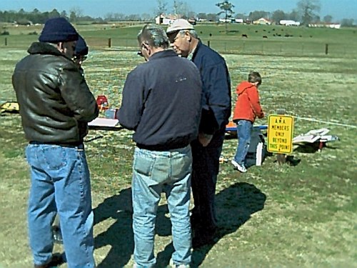
Anniston R/C Club
Fun Fly
Feb. 23, 2002
It was a cold and windy day for the fun fly, but several pilots endured the cold and participated in the three events. Event number one was the taxi contest where your plane had to stay on the ground and taxi around two markers, return to the starting spot and burst a balloon and cross the finish line. Cecil won that event. Event number two was the carrier landing where you had to take off and land within a marked area on the ground that simulated a carrier ship, the closest to the simulated grab line won. Roy Miller won that event. The third event was a bomb drop. We used styrofoam cups connected to our planes with rubber bands and a bomb made by placing three small cups together with weight in the bottom cup. Loren won that event. Overall it was a fun day and everyone had a good time with no accidents other than Jerry had his landing gear to fall off after takeoff on the last event. Jerry landed it with a lot of skill and had minimum damage to his plane.
 |
 |
 |
Stupid is as stupid does
By James Goss
What is the most unearthly and or embarrassing thing that has happened to you at the flying field? Let me get it started, this happened to me only yesterday at the field. We were having a fun fly day and everything had gone well and the field was opened for flying again. I was flying my new round disk plane and had flown it several times already. This time I cranked the engine and I noticed it was a little high on the throttle so I let it roll forward with the intension of throttling it down after it rolled forward. I brought the trim down but nothing happened, the plane just kept going and getting faster and faster. I began to run after the plane, but the disk was going too fast for me to catch up with. It was heading toward a fence and I just knew it would be damaged. It is hard to run while you are reaching down to grab your plane and at about two thirds distance across our field my feet got tangled and I began to roll like a barrel. I only had one thought in mind while I was rolling across the field and that was "What the heck happened?" I also had a thought to protect my radio! My next thought was "I wonder if anyone saw me". When I stopped rolling, the plane also stopped on its own. When I checked the plane I found the switch to be off. It must have gotten bumped when I picked the disk up to set it in front of my safety stops. With over thirty years of experience this just goes to show that anything can happen at the field to anybody at anytime. Now lets hear your story.
|
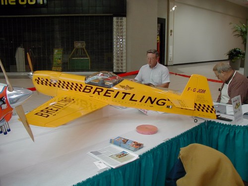
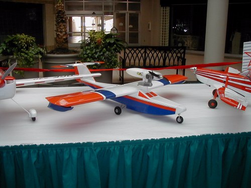
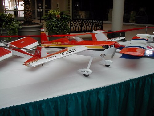
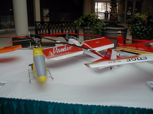
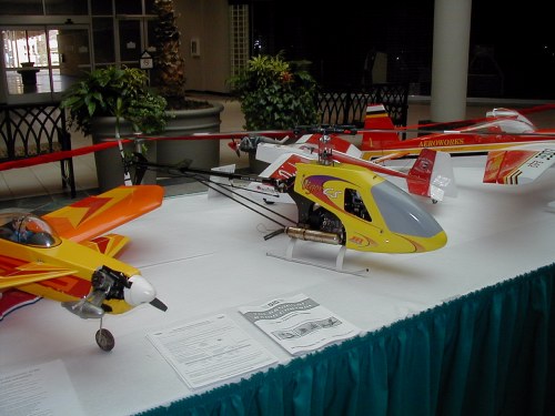
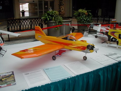
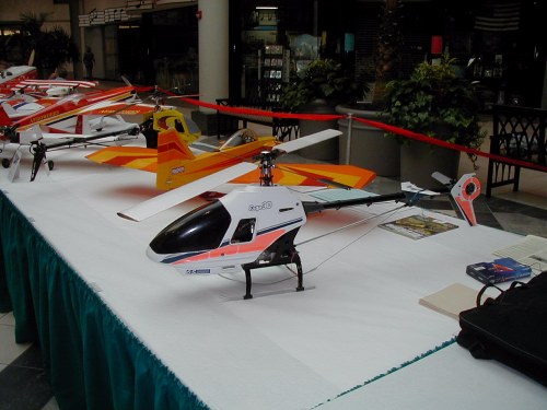
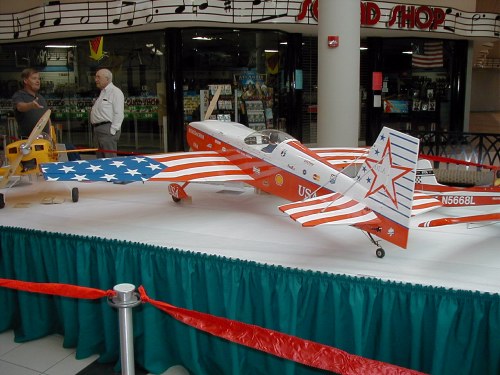
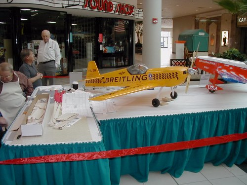
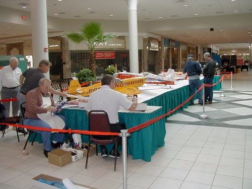
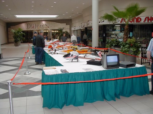
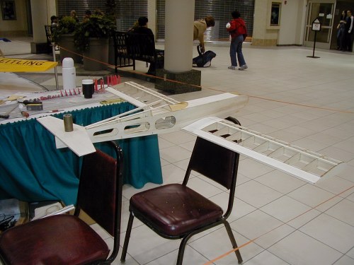
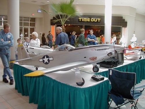
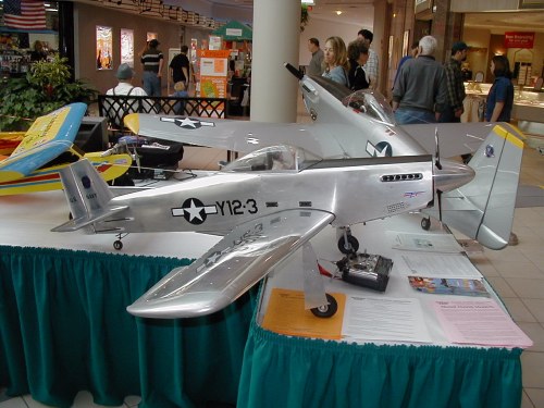
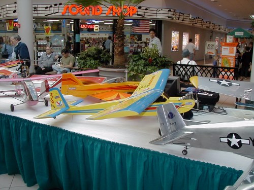
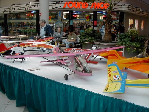
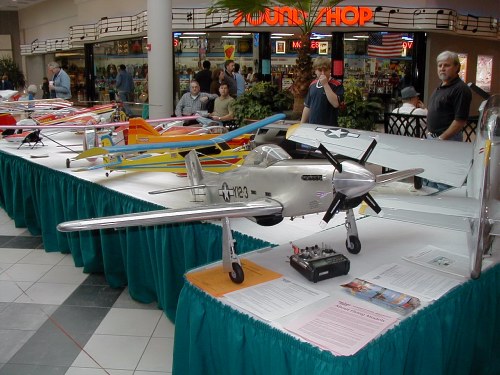
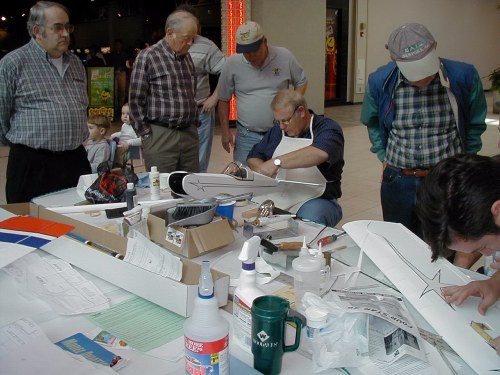
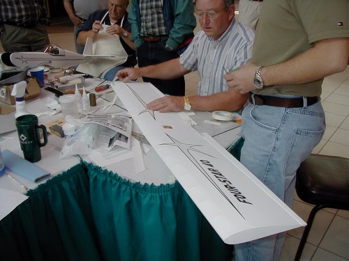
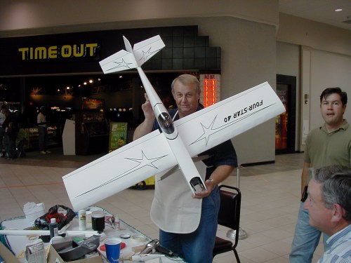
2002 Mall Show Pictures
Photos by Dr. Vic
 |
 |
  |
 |
 |
 |
 |
 |
 |
 |
 |
 |
 |
 |
 |
 |
 |
 |
 |
The Perry Georgia Swap Meet
The Perry swap meet this year (March 2, 2002) was very much like last years in that it rained all day lone and there were thousands of people in attendance. I went with Pat, Mike, Vic, and Steve in Pat's "jet" van. We arrived at around 9 am and started to look things over. Other members from our club that attended were Gene, George, Cecil, Larry, Lin, Loren and our good friend Glenn Florence. I was not looking for anything big this year and I don't think the other guys were either. Most of the purchases could be brought home in our pockets. I am already looking forward to next year and I hope it is not raining because they do have a lot of outdoor activity.
|
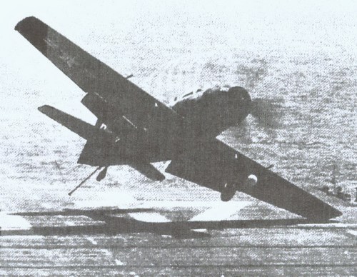
This photo was submitted by Ken and if you look real close you can see the jet stream created by the prop blast. This proves that the jet stream is no bigger in diameter than the prop and is funnel in shape due to the counter clockwise rotation of the prop. Here the icing is what allows us to see the jet stream and the pilot is giving it the gun in an effort to pull up before crashing. Unfortunately the plane ended up in the water. Thanks Ken for this nice action photo.
 |
Technical Tip
There is nothing worse than to have the balsa split and fly apart around the edges of a hole you are drilling with standard twist drill bits. If you are lucky enough to have a set of forstner bits you will get a nice clean-cut hole if you use a backing to drill on, but even with forstner bits you should still follow this tip. Before you drill apply thin ca glue around the area of the hole. This works better than masking tape plus it also strengthens the wood. With ca applied the balsa will cut nice and clean if you take your time and don't apply too much pressure. This works great when you have to countersink a hole such as is needed on some of the wing bolts on large planes. You probably have used thin ca when you are drilling the holes for your wing bolts. After you tap the hole with a ¼ x 20 tap, place a few drops of thin ca on the threads, let dry and run your tap through again. So why not use thin ca any time you drill holes in balsa or any other wood to keep the wood from splintering.
|