Cow Patty News
Monthly Newsletter
March 2002
The Anniston RC Flyers

God Bless Amereica
What's in the newsletter this month?
|
February Club Meeting Minutes
The minutes for this meeting are not ready and will be added as soon as they are.
|
Questions and Answers
Question Concerning Ultracote Covering
Hello James,
I have finally managed to get started covering the Super Sporster. I plan on doing the wing in a multi color scheme, but am not sure how to proceed. Is it safe to cover the wing, open bay, in pieces with an overlap of about ¼- inch. I have tried it and can get the seams, but they don't seem to be very strong. Would it be better to cover it with a base coat in a solid piece over the entire wing and then add the colors...... If I have confused you, look at the Hangar 9 Aresti in RC Modeler. That is kind of the effect that I am after for the wing. I am not really worried about so many seams on the fuse since it is almost all sheeted. Any Suggestions would be appreciated.
Thanks
Reply to Ultracote Question
Good to hear from you again. I think you will get the best results if you cover the wing in the base color like you said. I have used the seam method and would have trouble some of the time with the seam over the open rib bays. They would sag in the future. Covering the wing with a solid piece of covering will provide plenty of gripping strength for all the top colors. If the front leading edge sheeting is solid and is going to be a different color from the rest of the wing you can stop the base color about one inch in front of the main spar and then apply the front color over the wood.
If you really want to get a good job with few bubbles use this method. After you apply the base color, cut the trim color to its finished pattern and lay it over the base color and secure it with a few pieces of tape on the ends so you can still pick up the edges. Use a pencil to place a mark about ¼ inch inside the pattern all around the edges. Remove the trim color and use a peckerwood to place hundreds of tiny holes inside where you have outlined.You will feel sad about punching holes in your freshly covered wing, but it is for the best finish. With your iron set at about 230 degrees you will be able to secure the trim color without shrinking it. Ultracote bonds best at about 230 degrees with no shrink. For shrinkage increase the temperature as needed up to 300 degrees for max shrink. If you have the iron too hot you will distort the edge lines. I like to use the backing paper that comes on ultracote instead of an iron sock. The temperature changes too much with a sock. The paper does a nice job if you place the polished side toward the iron. It distributes the heat and helps prevent distortion in the trim color edge lines. Good luck! James
Ignition Question
I realize there should be 10-12" between the ignition and the radio-switch etc for interference problems, but does that include everything, like the throttle servo or kill switch servo (or electronic kill switch) or can those servos ( and there leads) be closer as long as the rcvr-battery- switch has seperation
Reply
This includes everything that has conductors going back to your receiver. I had this problem of glitches a few months back because I had mounted the servo for the throttle up front of the firewall. I knew better but I wanted to see if it would really make any difference. Believe me it did, I had the mother of all glitches. Also watch out for tail wire braces that are metallic and form a closed loop. James Goss
|
Seeing the Future
By James Goss
You may think this article has nothing to do with the R/C hobby, but in a way it does. Being able to see your plane in flight is more important than any other aspect I can think of. The phrase You can't fly what you can't see is having more and more meaning for me, as I get older. In our society it seems to be common for us humans to require eyeglasses, especially for reading small print, by the time we are in our late forties. Just look around and see how many folks you can find who are in their late forties and are not requiring reading glasses to see small print. I know that I was 49 or 50 when my eyes started to go south and my arms kept getting shorter and shorter until I could not reach far enough to read small print. I don't think you will find many eye doctors that will agree with what you are about to read. Of course selling eyeglasses is there business. Why do you think the oil companies are not interested in running your car on water? Where would the profit be? Eye doctors could advise a person of alternatives before they sell us eyeglasses if they had a mind to. This system that I am going to describe for you is very simple and I think it really does work to improve your eyesight. I am not recommending that you should do this, but I thought you might like to read about it.
Benjamin Franklin did us a great service when he invented eyeglasses, but he would have been of more service to us if he had given us the following information: Exercise your eyes! That's right, exercising the eye muscles is the key to keeping your eyesight. Your eye has six muscles that control its movement and holds the shape of the eyeball intact. These muscles are just like any other muscle in your body except they are very tiny in comparison. Like other muscles in your body they will also loose their muscle tone if they are not used on a regular basis. Muscle tone describes a muscle that has firmness and is capable of doing more work when called upon to do so than one without tone. To have muscle tone the muscle must be exercised on a regular basis, so exercise is the key to muscle tone.
Check this out, walk up to someone from his or her side and address them as to get their attention. They will not move their eyes to see who it is; they will move their whole head around to see who it is. Of course their eyes will move a little, but can see what I am talking about. It is a fact that we move our head and neck instead of our eyes to see our environment. Our neck gets plenty of exercise while our eyes get little if any. Have you ever noticed how good it feels to rub your eyes when they are tired? Of course your eyes have no feelings so it is the muscles that are responding. If we started exercising our eyes at an early age, say in the teen years, we may never need glasses for reading purposes. It may even help other eye conditions as well. When you are born, or shortly there after, your eyes form their perfect shape for being able to focus the light from objects just right so you will see clearly. Everything is down hill from there. As we get older and our eye muscles get out of shape and weak, the eyeball is allowed to change its shape. This causes the focal point of the eye to be different from what it was at an early age.
I know it is the shape of my eye that is failing me at this time and here is a simple test to prove it. Remove your eye glasses if you use them and hold some writing in front of you that you can't quite make out the print. Now squint your eyes and the print will clear up. You are using your eye muscles to squeeze the eyeball back to its old shape that gives the proper focus. So I am sure it is the six eye muscles that are at fault and not the eye itself when it comes to reading small print.
About seven years back I was attending a video science conference held in Colorado Springs. I had just been selected the Technical Teacher of the year for 1995 in the state of Alabama and as a result I had $1000 that I could spend in the science field. I used this money to purchase science videos dealing with all types of future science discoveries, one of them had an eye doctor discussing care of the eyes by exercising them. She had a volunteer from the audience to come on stage. This person did need reading glasses and was given a list to read without her glasses. The reading print got smaller and smaller as she scanned down the page. She was able to read a few lines and was asked to mark where she stopped. The eye doctor had her to do some simple eye exercises that last for about one minute and had her to read the page again. This time she was able to read several lines past where she had marked before. Several other volunteers were ask to do the same test and all had the same results, they had better focus after the eye exercise routine. The vision would go back as time went on, but it did prove that exercise would help the eyes. With regular eye exercise each day the vision will slowly improve.
I have started this program several times since then but always got sidetracked with work and all. I have started the program again and plan to stick with it this go around. It only takes five minutes each day and if I can't spend five minutes to improve my eyes I am in really bad shape. I have also found that if you get your heart rate up before you do the eye exercises the results are more positive. I like to walk on the treadmill for about ten minutes before I start the eye routine. This seems to get the blood really flowing and the eye muscles can get pumped. Just like any other workout your eyes will feel very relaxed when you finish, and you can seem mush clearer than before.
The exercises mainly involve moving the eye to their extremities or the outermost perimeters of the eye instead of moving the head. Keep your head fixed and looking straight ahead during all the exercise movements. Exercise Number One: Move the eyes from 9 o'clock to 3 o'clock in a level line. Hold the eyes at the maximum position for about three seconds. Do about 15 repetitions for each of the exercises. Exercise Number Two: Move the eyes from 9 o'clock through 12 o'clock over to 3 o'clock in an arch movement. Number Three: Scan your eyes from 9 o'clock through 6 o'clock to 3 o'clock. Number Four: Move the eyes in a complete circle while at their extreme position, both directions. Number Five: Close your eyes and squeeze them as tight as you can and then open them as wide as you can. Number Seven: Using your index finger rub across the top of each eye starting at the top of your nose and move toward your ear. Number Eight: Same as seven except rub across the bottom of the eyes starting at the nose and rubbing toward the ear. While rubbing let your finger put a little pressure on the eye, not too much but just enough to feel it. Number Nine: Finally, pinch the skin on your cheek just below the eye and give it a good shake for about 30 seconds. The workout will take about five minutes and when finished your eyes will feel refreshed. After a few weeks you will want to increase the eye workout to ten minutes because the muscles are getting stronger and it takes more to tire them.
The six eye muscles will have had a good workout and with time your reading vision will improve. Remember, we have been letting these muscles sit mostly idle for the last fifty years so it will take a little time to turn things around. If we do the workout every day for about three months I think we will see some progress. You may even want to do the routine two or three times a day for faster results. So I look forward in seeing the future and hope to be able to see those little model planes for many years to come. Let me say again I am not recommending that everyone should try this eye workout, but I thought you might be interested in reading about the process.
|
Why Men Love To Fly Model Planes (The Real Story)
By James Goss
I have been trying to figure out why we love to fly and build model planes as mush as we do. There is a lot of work in building and setting up a model plane to fly, so it can't be because there is no work involved. It requires many trips to the flying field to learn how to fly in the first place so a lot of effort and energy is required. As you already know these babies don't come cheap, so it can't be because we can afford them. They are a lot of fun to fly, but how about the crashes and rebuilding, not as much fun there! It can't be because of the fame and glory because most of us are average weekend flyers with the only adoration and praise being that we get our planes back home in one piece. So what is it that keeps us going back to the flying field year after year after year???
I think the real reason might be that men like to be obeyed and have their orders or commands complied with without any feedback. When we tell our planes to turn right, they turn right. When we tell them to go up, they go up. When we tell them to roll over, they roll over. Whatever we ask of them they do it and keep on flying without any feedback. Where else could we get this kind of attention and really be in command? Only at the flying field where we are the masters can this happen. When at the field we are in fantasyland where we can get away from all the hassles of everyday life and relax. While we are flying there is no time to think about anything else except flying that plane. At times I am sure our wives think we are in this hobby to simply aggravate or irritate them, but this couldn't be further from the truth. If we wanted to do that we would simply stay at home where we are master of nothing, (just kidding). Actually if it wasn't for our beautiful wives we wouldn't be in this wonderful hobby in the first place. They give us rock solid support when we really need it and even help out at field events such as cookouts and fun flys.
So the real story behind us men loving to fly so much is our wives creating a loving environment at home that enables us to go to the field in the first place. Without their support our hobby would not be what it is today. You know what they say;" Behind every successful pilot there is a woman". I would like to take this time and thank all our loving spouses for their support of out hobby and for putting up with our obsession with this compulsive hobby of ours.
After I put this article together I ask my wife Mary to read it to see what she thought. She said it looked ok to her so I thought this would be a good time to tell her that I needed to buy an engine for a giant scale project I was building. I told her the engine only cost $1650 and I would need it next month. She replied sure honey, whatever you need go ahead and get it to help support this wonderful hobby. Then she replied "But you didn't think I would fall for this did you"?
|
Propellers
By James Goss
In this article I would like to first describe the props we use in our hobby so anyone new to the hobby can have a better understanding of props. Next I would like to go a little deeper into this subject of props and explain prop efficiency and how a progressive prop such as the 26 x 8 - 12 operates. I know there has been a lot of confusion about progressive props and why they are used. I know this because I am the one that was confused until I did some research on the subject. The prop is just as important as the wing or anything else on the plane. Without a prop you could have the best engine money can buy and not be able to move your plane one inch. A propeller is really a spinning wing and if you look at a cross section of a prop you will see that it has an airfoil just like a wing has. It has an angle of attack and this angle changes along the length of the prop.
Our propellers rotate counterclockwise when looking at the plane from its front. As the prop's leading edge begins to rotate or move downward, air is forced down and behind it. This creates a void of air above the prop at its trailing edge and there is now a pressure differential created between the leading and trailing edges of the prop. That is to say that the area around the bottom of the prop is now under greater pressure that the area at the top of the prop. A positive pushing pressure at the bottom and a negative pulling pressure at the top is another way of stating it. As the prop rotates around, the reference to the top and bottom is constantly changing so we will just think of the top and bottom as being the top and bottom of the plane. Do you think of your plane as being pushed or pulled through the air by its prop while it is flying? Well it is both; the prop is pushing and pulling at the same time. The prop is a pump just like any other pump and is pumping air, so it has a high-pressure side and a low-pressure side. It pulls air in the front and expels it out the rear at a higher velocity and forms a jet stream. This jet stream leaving the prop is smaller in diameter than the size of the actual prop and is the key to understanding the operation of a prop.
By the jet stream being smaller in size than the prop, the velocity of the air will increase and provide what we call thrust. Thrust is measured in ounces or pounds of thrust. A good example of thrust can be found in your garden hose. When you adjust the nozzle on the end of your garden hose so the water will reach to its maximum distance, what is happening? Are you adding more pressure to the water? It was discovered many years back that the volume of liquid entering a pipe must always equal the volume leaving that pipe. If the pipe has a taper toward one end then the water will be restricted and resistance to the flow will develop. The same amount of water must still leave the pipe as is entering so in order for this to occur one thing must happen, the water must accelerate through the pipe. Its velocity will be increases in order to maintain an equal volume flowing through the pipe. On your garden hose the water leaving the nozzle has less pressure than the water entering the nozzle, but more velocity. The obstruction or taper in the nozzle becomes an orifice and has a high and low-pressure side. When you increase velocity, pressure will go down. Our propellers work the same as water flowing through a pipe. By the diameter of the jet stream being smaller than the prop's diameter the air has to accelerate in order to maintain the same volume of air flow. This increased airflow is the thrust that our planes need to fly through the air. The diameter of the jet stream is smaller because the prop is turning in a circle and forces the air into a funnel some distance behind the prop. Think of it as having a giant piece of flat rubber that stretches from the prop to the tail of the plane and the rubber is the same diameter as the prop. As you turn the prop by hand the rubber will reduce in diameter at some distance behind the prop as the rubber twist. With the prop turning at high speeds the air will do the same thing and form a funnel shape.
The diameter of a prop tends to determine how much thrust is developed by a prop. It is not the pitch of the prop that determines thrust; pitch determines the speed of your plane. The larger diameter props will develop more thrust than one of less diameter. This was puzzling to me at first but I soon realized that it was just like the garden hose. A larger diameter prop tends to produce a jet stream that has a smaller diameter ratio to that of the prop. It's like turning the nozzle on your garden hose to get more distance. A larger diameter prop has the power to reduce the jet stream to a tighter funnel, thus more velocity for the air and more thrust for our planes.
As stated above the pitch determines the speed of your plane. Pitch is rated in inches and is stated as 10 x 6 on a prop in this example. 10 being the diameter of the prop and 6 is the pitch. If the prop was 100% efficient, each time it makes one complete revolution your plane would advance 6-inches through the air. It is like screwing a screw into wood, each time you rotate the screw it advances further into the wood. If the prop was turning in a solid material it could advance 6-inches, but in air it will not. Unlike a solid the air will compress and distort as the prop turns and this creates what is known as slip. Prop slip is the difference between the calculated speed of the air through a prop and the actual speed of the air. A 10 x 6 prop may only be rated as 85% efficient, so each time it rotates it will only pull the plane 5.1 - inches forward and not 6 - inches. What I would like the manufactures of props to tell us on each prop is how much slip they have or their efficiency rating. Knowing this we could better make decisions about which prop to buy. It could be stated as 85% efficiency at 8,000 rpm or something like that. By and large we need to know more about our props from the manufacture because like I said above, the propeller is one of the most important components on our plane if not the most important. Another rating I would like to see on each prop is its weight so we could compare props without having to weigh them. Is this asking for too much?
Now comes the good part, progressive pitch propellers. These are confusing so I would like to give you my thoughts on the subject. An example of a progressive pitch prop would be a 22 x 6 - 12. The pitch is stated as being 6 and 12, this means that the pitch of the prop progresses from 6 to 12 in a linear manner. At the center of the prop, known as the root or hub, the pitch will be 6 and progress to the tip where it has a 12 pitch. Remember that pitch is simply describing the twist angle of the blade. Here is an example of what I mean about this subject being confusing.
This question was posted on RC Universe:
PROGRESSIVE pitch Props like 18x6-14
Someone help me understand what a... say for instance a
18x6-14 pitch prop does for me as compared to a 18x6 or 18x7 pitch prop.
I have a S.T.2300 in a 25% Cap 232. Just wondering what would be the best power prop in this airplane.
Another One
I thought it is the other way around????
I have a 14x6-10 and it sure looks like the root has a higher pitch than the tip.
Here is my reply
You are right; it does look like the highest pitch is at the hub. This is the case with all props; you can see that a higher angle is definitely at the hub. This is because as you approach the hub from the tip of the prop, that portion of the prop is moving slower than the outer portion of the prop while rotating through the air. As you move toward the tip it actually looks like there is less pitch to the eye, but because the prop in that area is traveling faster it generates the same pitch equivalent, or air pumping ability, as at the hub. If the prop maintained a true pitch that you could see all the way down the length of the prop, the tip would process much more air than at the hub and this wouldn't work. So the pitch of a prop is an average determined by the increased speed of the prop as you travel toward the tip.
I think a progressive pitch prop will be more efficient because of the following. Think of prop pitch as being the same as the pitch on the gears in your car. Higher pitch will equal better top-end performance and lower pitch will improve low-end performance. The prop will be more efficient at low speeds with the low pitch section of the prop and more efficient at high speeds with the high pitch section of the prop. No props are 100% efficient because of a thing called slip. Slip is the difference between the calculated speed of the air through the prop and the actual speed of the air. A constant pitch prop may be 85% efficient in pumping air, that same style prop in progressive pitch may be rated at 88% efficient when flown at various rmp. It would depend on what type flying you do as to where you would benefit from a progressive pitch prop.
Let me say again that you can easily see the angle of the pitch is greater at the hub than at the tip. Again this is because this section of the prop travels through the air at a slower rate than does the tip. As an example lets say that we have a 12 x 6 prop turning at 10,000 rpm. The section of the prop 1-inch from the hub will be traveling at 59.5 miles per hour while the tip will be traveling 356 miles per hour. From this you can see the section of the prop at the hub will need a larger angle to maintain the same airflow as the tip. A progressive prop will allow the tip end to produce a great deal more airflow than at the hub. High pitch props tends to have more slip and low pitch tends to have less, so you get an overall improved average efficiency rating for the prop that is going to turn at multiple speeds.
If a prop had the greatest angle of pitch at the tip instead of at the root, it would be referred to as a regressive pitch prop. I know they use this type prop on some boats for special applications. I wonder how it would work on an airplane? Well I know it would create a lot more noise with a higher angle on the tip because so much more air would be placed in motion at that high tip speed. This arrangement would also distort the air coming off the tips and that would change things. When one blade of a prop cuts into the air it leaves a trail of upset air for the next blade to cut into. The trailing blade is a little less efficient because of this distortion of the air. Of course the most efficient prop would only have one blade for that reason, but it would be a real pain to balance.
That reminds me; always balance your prop because some of them will really be out of balance when you get them, especially the glass filled props. Dubro makes a fine prop balancer for large props that your magnetic balancer will not support. It will balance any size prop, even a 36 inch if you need one that large, I do for my half scale Cap. The larger the propeller the better this wave balancer operates. Stay with your magnetic balancer for props less than 16 inches in diameter.
|
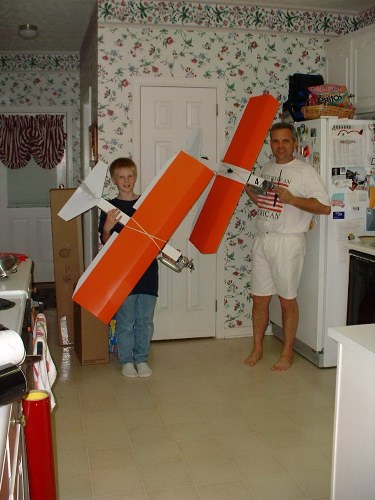
Here Is The Correct Way To Hold A Coroplast Wing While Gluing
This is how Jim Woodard clamps down his coroplast wings while building a SPAD ( Simple Plastic Airplane Design) plane. These lead weights are Jim's sons and from left to right they are Jeffery, Matthew, and Zack. Matthew is already an rc pilot and has flown at the Munford field with his dad Jim. I guess this proves coroplast wing construction to be really strong. I could truly use these weights in my shop because they are self propelled, just tell them to jump up there.
 |
Here is Jim's newest creations in the world of SPAD design planes.
 |
Flaps and Models
By Garland Minor
Over the past few years I have noticed that most Modelers, with the exception of the scale Modelers, never use flaps if they have them installed and are not willing to build them into their models. The reason being is that most R/C Modelers have a misconception of the purpose of flaps. That misconception is backed up by the comments heard at the field when flaps are the topic of conversation. Comments such as; " When I used flaps they didn't slow down the plane", and "All they do is cause the plane to climb and float", and also "I had to use reverse flaps to get the plane to land". Flaps are not intended to slow the airplane, however airbrakes are. Flaps are designed to give the plane additional lift so the plane can fly at a slower speed thus reducing the stall speed and allowing a slower approach.
The reason the plane floats or climbs when the flaps are extended is due to the additional lift created. This additional lift has to be compensated for with a little down elevator in order to maintain a constant rate of descent. You have to be careful that you do not increase the angle of attack so that you stall before reaching the runway. Ideally you should be at stall speed and run out of elevator just as the wheels touch the runway.
With most of the computer radios you should be able to mix the elevator with flaps so that a slight amount of down elevator is added when the flaps are extended. With some radios this might be a problem as the computer program is set up for acrobatics so that the flaps, if used, are slaved to the elevator in order to achieve snapper maneuvers. This is not what we need in order to achieve a slow approach speed and a constant rate of descent. How much mixing do you use? Start with a very small amount and then adjust as needed to achieve the desired effect.
With a little practice you will be able to make flaps work for you the way they are intended. When you learn to land using flaps keep in mind that they can also be used in takeoffs to reduce the distance needed to get airborne, but note that the plane will sink somewhat when the flaps are raised. Have fun and don't be afraid to try them.
|
Mall Show 2002
The 2002 mall show in Oxford was a real success this year. We set up Friday morning at 7 am and left the mall at 12:45 that night. Came back Saturday at 7 am and left again at 8 pm. We had plenty of planes on display and hundreds of mall shoppers came by to look and talk with us. The club had an added attraction this year; we built a complete airplane in two days, a Sig four-star 40. We framed it Saturday and covered it Sunday, we finished it at 2 pm that evening .The plane was then raffled off Saturday evening at 5 pm and a fellow by the name of Bill Folsom won the plane. His wife had purchased two raffle tickets Friday morning and said that she would win the plane and she did. Mr. Folsom is an RC pilot so the plane should have a good home and maybe a long life. Our club made a little money on the raffle so we might do it again nest year.
All club members that worked the mall show will receive a mall pin from the AMA this year. Cecil is turning in a list of all our names and we should be getting them in a few weeks. The mall show is a really good way to attract new members for our club. We had an rc simulator set up, provided by Terry, and it stayed busy the whole show. We also had a vcr going with tapes of rc in action, provided by Ken and Jerry. Over all, everybody had a good time, but it was hard to stay away from the field on such a nice day.
|
Gas Engines With Two Coils
By James Goss
Have you ever wondered why some of our gas engines have two magneto coils while others have only one? Zenoah engines are an example of what I am talking about with their G-45 and G-62 engines. They each have two coil modules with one located next to the flywheel. To have an electrical generator it requires three things: a conductor, a magnetic field, and relative motion. Relative motion simply means that the conductors are moving past the magnet or the magnet is moving past the conductors, it will work either way. In a generator the conductors are normally wound as a coil because it is the number of turns that determine how much voltage is generated. Speed at which the magnetic lines of force cuts the conductors also determine how much voltage is induced into the conductors.
The conductors are also wound on an iron core because the iron is a better conductor of magnetic flux that is air. The core will couple the magnetic energy to the conductors with less loss of flux lines. Having an iron core will increase the voltage induced into the coil at least ten times. This type of generator is referred to as a magneto because of the permanent magnet used to initiate the process. When the magnet on the flywheel scans past the coil's core a pulse of voltage is induced into each turn of wire on the core. The voltage across each turn of the coil is only about .5 volts or less, but each turn is in series with the rest of the turns and they all add up to a total voltage that is the sum of all the turns voltage. These coils may have several thousand turns and will produce the high voltage that is needed to ionize the plug gap. It takes about 10,000 volts to ionize the air and arc across electrodes that are spaced 1/8 of an inch. Plug gaps are normally set at .02 to .03 inches so you can see that a 10,000-volt potential would produce a nice arc.
Magnetos that use only one coil only needs two wires coming from the coil. One usually goes to the chassis (ground) and the other is the high voltage lead that goes to the spark plug. On older engines you would find three leads coming from the coil. One to ground, one went to the points, and the other was the high voltage lead to the spark plug. A coil with three leads is actually a transformer known as an autotransformer. This transformer has no isolation between the primary and secondary windings, as does a regular transformer. The points was placed in series with the primary so when the magnet passed by the magneto core and was in just the right position, the points would close and allow current to flow through the primary which induced the high voltage in the secondary. The points only stayed closed for a very short period of time and when they opened an arc would develop across their contacts because the points were opening an inductive circuit. To help prevent this arc from damaging the point's contacts a condenser (capacitor) was placed across the contacts. When the points opened, the capacitor would charge, when the points closed the capacitor would discharge. This action would help prevent the points from arcing.
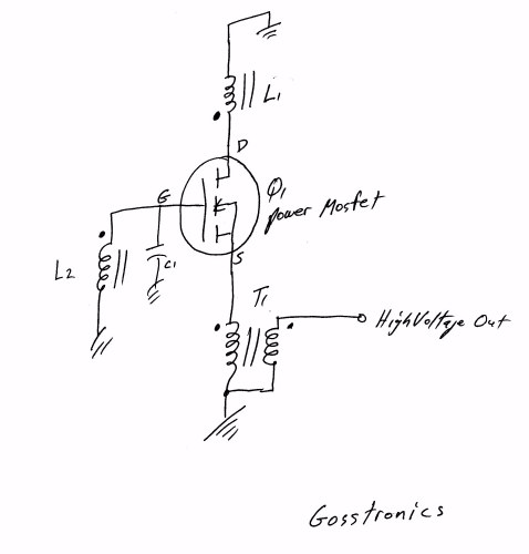
As you probably already know engines such as the Zenoah has no points or capacitor as such. Instead they have a transistor ignition that sets the timing so the high voltage pulse can only occur when the magnet is in the correct position for the plug to fire. You may wonder where these electronic parts are located because you have never seen them. As you probably already know engines such as the Zenoah has no points or capacitor as such. Instead they have a transistor ignition that sets the timing so the high voltage pulse can only occur when the magnet is in the correct position for the plug to fire. You may wonder where these electronic parts are located because you have never seen them on your engine. They are located in the module with your magneto pickup coil as an integral part of the coil. Below you will find a diagram of a very simple transistor controlled magneto system. This may not be what Zenoah is using because I have never cut into one of their coils, but it is a workable circuit. If anyone would like a detailed explanation of the circuit just let me know. This circuitry would be located in the first coil, the one that the magnet scans. As you can see there is only two wires coming out ot the coil body, the high voltage lead and ground.
 Having a coil that both generates and steps up the voltage, like on a standard magneto, is an economical way of doing it but using two coil modules is a better way when transistor ignitions are used. The first coil has the responsibility of generating a control pulse at the right time and not worrying about the high voltage being generated. With lower voltage the module can be insulated for less voltage, this is cheaper and easier to do when small voltages are being used. The high voltage is the job of the second coil module. It takes the control pulse from the first coil and transforms the pulse to a useable high voltage to fire the plug. This coil is an autotransformer with three leads, a ground, a lead to pickup the incoming control pulse from coil one, and the high voltage output. The two coil modules work together and if either one goes bad the ignition will shutdown.
If you are running an engine such as this you probably thought you were not using an electronic ignition, but technically you are. You are not using an ignition battery like we do on the full electronic ignitions because the ignition is getting its operating power from the magnet. The correct description for this type ignition would be to say that you have an electronic switched magneto ignition.
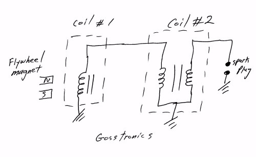
You may also wonder why an ignition needs a switch in the first place, be it points or transistor. Without a switch to control the firing system the high voltage pulse would be erratic in its time duration. Remember that getting the plug to fire when the piston is in the correct position around top dead center is what it is all about. If the high voltage pulse reaches its peak a few milliseconds before or after it should, the engine is going to be out of time and strange things will happen. So a switch will only allow the high voltage pulse to exist while in time with the piston's power stroke. More on this down below. Here is a diagram that shows the relationship between the two coils. Electronics part of the system is omitted.
|
 |
Why We Need An Electronic Switch For A Magneto Coil
By James Goss
After reading the article above you may be wondering why our gas engines would need to have any electronics at all for the coil to operate. If you remember the old ignition points that were mechanical in their operation and were found down under the flywheel assembly then you probably already know why we need the electronic switch. Also do you remember how hard it was to get that flywheel off without the puller you didn't have when you needed it just to get to the points? I normally used a hammer to hit the top of the crankshaft while holding the flywheel and it would finally come off the shaft. That wasn't good for the magnets because severe jarring will weaken a magnet. In those days I didn't care about the magnets, I wanted the flywheel off.
By the points being mechanically operated, this meant that they would wear out and have to be replaced every so often along with the condenser. (Condenser is the old name for a capacitor). Even though the high voltage pulse was generated by a magnet embedded in the flywheel, it was the job of the points to close their contacts and allow current to flow through the primary of the coil (autotransformer) at the precise time the high voltage pulse is needed by the spark plug. If you were trying to use the coil without any control timing of the current through the primary, there would be a high voltage pulse but it may occur too soon in time. Because of its pulse width the high voltage could make the firing erratic and sometimes it would fire at one time and the next cycle it would fire a few degrees sooner or later. This is because the spark plug operates by having a voltage applied to its electrodes that will ionize the air between them and conduct electricity. If this voltage is allowed to build up with time from zero volts until it reaches 10,000 volts and breaks down the gap, it will be erratic for sure. Instead, if the 10,000 volts is applied all of a sudden, the gap will break down at the same voltage amplitude each firing cycle and we will have the correct timing needed to run the engine.
Each time the points operated there would be an electrical arc as they opened because they are opening an inductive circuit. Any electrical discharge such as this can interfere with our control system or any receiver such as radio or television. To prevent this interference problem and to also extend the life of the points, a capacitor is placed in parallel with the breaker points. Each time the contacts on the points open the capacitor will charge and prevent the electrical arc that would damage the contacts. Each time the points close the capacitor will discharge.
So it is mandatory to have a device to control the time at which the high voltage pulse can be generated. With the advent to the transistor it was only a matter of time until the mechanical points were replaced. Solid-state reliability has taken over in our ignition systems and the breaker points are mostly history now. If a transistor is operated within its limits it may last for the lifetime of our ignitions. This is why we don't have access to them on our engines and if they do go bad we replace the whole unit. So remember each time your spark plug fires it does so because a transistor told the magneto to do so.
The electronic ignition we have today differs from the magneto in that it does not use a magnet to induce a voltage into a coil of wire. Instead it generates a signal by an electronic oscillator that produces rectangular waveforms at a frequency that is determined by a Hall sensor. A magnet is used but it is very tine compared to the magnet found on magnetos. The hall magnet does not generate any voltage like the magneto magnet does into a coil of wire. The tiny hall sensor is really an integrated circuit with the hall sensor being a small part of the chip. The hall sensor works by setting up a polarity when it is exposed to a magnetic field. This tiny dc voltage is amplified and used to turn on a transistor switch that provides a voltage (usually 3 - 5 volts) to the ignition module to tell it to fire the plug. Most magneto systems had a higher voltage output than does the electronic ignitions. Magnetos are reliable but they are heavy. There is much more to go wrong with an electronic ignition because of the number of components involved.
|
New Planes Taking To The Air
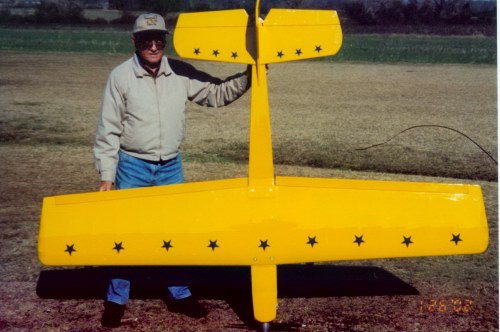
Here is George and his new Big Bee. This plane has a 96 inch wing span and is powered by a G-23 engine. Total weight is 16 pounds to the ounce. This is one giant plane and the yellow really shows up in the air. George has added a pair of 5-inch wheels and they roll smooth on our grass field.
 |
Here is Jack Holland and his new AT-6Texan. Jack did a nice job with this Great Planes ARF.
 |
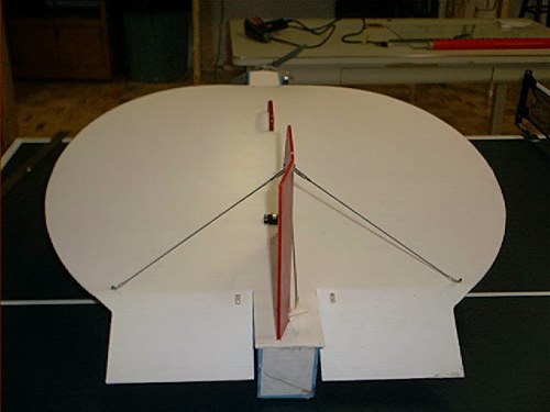
This is a 32 inch disk plane that I have just finished. This picture is not of my plane but looks like mine. I have not flown it yet but will soon. I will let you know how the flight went. This plane can be built in a couple of days if you wanted to and only costs less than $10, minus hardware. If it flies I plan on building one for each day of the week.
 |
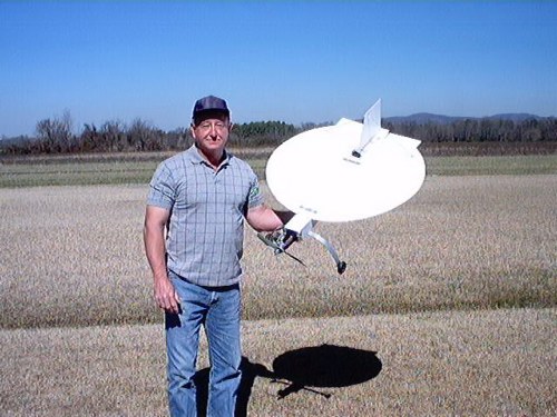
Update
Here is the finished product, and it really flies well, it has some moves all its own. I have got to get some color on it so I can tell its orientation in the air. As it turns out, this little plane is one of the most fun flying planes I have built. How can a little inexpensive plane such as this fly so well? Its wing is only 4mm thick and will fly inverted as well as it does upright.With a .46 engine it will hover as good as any normal plane. When landing you can point the nose up and give it a little throttle and it will hover to a landing. I now have about ten flights on it and I think there is going to be one of these little guys in my hangar from now on.
 |
Here is Lin Smith and his new Sea Master. Lin really did a nice job on it and it is absolutely beautiful.
 |
 |
Radio Impound
By James Goss
We have been discussing radio impound at both Talladega and Anniston club meetings. I have surveyed about fifty RC clubs to get their views on impounding. I plan to run some of them next month so you can get an idea of what other clubs around the country are doing. This month I would like you to read what one man has to say about impounding. This reply is the exception, most were very helpful and I think you will enjoy reading them next month. This reply has been pulled word for word so you can get the full impact. Let me say that none of the following has been edited by me; spelling for sure has not been edited. It is rather long, but you need to read it all if you have time.
|
program wpourme
Member
Posts: 305
From: richland,TX
Registered: Aug 2001
Board pin and Impounds are great untill you get a wise A bringing them down left and right.
I was a believer in the Honest here the people took the time to talk and work things out, untill the pissers showed up and would try to bullie the younger guys over EVERY move. This was of course at the larger member fields.
It is nice to be a small club, quiet and away in the distance, but watch out in the larger groups where nastie neighbors and club guys are around.
It is usually the older ornery flyers that cause the problems, the guys that do not bring planes to fly, but always bring attitudes and personal troubles to the field.
Next thing you know you are shot down and or in fighting with the old farts and cussing the hobbie alltogeather.
Nobody would need Inpounds at all if the Mr. Nastiees of the world would shut up and let the younger guys have fun like they had when the hobbie was just takeing off in the 50-60s-70s.
How about we Impound the Old Farts? or clip a Neon pins on there ears so we can all see who spoils the fun at the fields.
I really vote on this Whole NEW! system and that puts an end to all the old board and impound stuff, then we can fly without any Alstimers/Oldtimers forgetting to turn off or leaving there box on.
leccyflyer
Member
Posts: 121
From: United Kingdom
Registered: Apr 2001
Okay I'll bite.
This "new" system has a 100x booster? Does that mean the radiated signal is 100X greater strength? So when everyone has one then everyone's signals will be 100x greater strength? What happens then, other than all the flying fields having to be 100 times further apart?
Leccy
Redback
Member
Posts: 207
From: Sydney, NSW, Australia
Registered: Jul 2001
Better still.
As I read it this system detects an interfering signal and boosts the Tx output accordingly.
However, the interfering signal needs to be measured at the Rx, as this is where it will cause the problems. No use trying to measure at the Tx because the field strength from the Tx will overpower all but the strongest interfering signal.
So, the Rx will need to be able to signal to the Tx that an interfering signal is present. In short a backward channel with a Tx of its own.
Pourme, if you really invested money in this I suggest that it's soon gonna be poor you.
------------------
Terry Goddard
pooshoedu
New Friend
Posts: 17
From: Irelund
Registered: Feb 2002
Yes it is I, Pourme,
The invests I have taken part in,(68 to date) have only 7 that did not bear fruit.
The system has not been proven wrong in 2yrs of testing and over 15 channels have been on at once to over ride it. Still no luck.
I have used it on my x box and not a chance of getting in or siginal blerps when this fires up.
Wife's brother is a electronic/computer engineer and work for robonics pharmicy engineering corp. Wife's father is a Ford Areo space rocket engineer/scientist and worked on the first model of the Global Postioning system. Who better to resurch these systems and to get infomation where to invest and all?
Looking at the system manuels and all both parties where more than inpressed and if you could read the Lit, you would know.
Patent and Production are being setup for operation/marketing in the trades by 2004.
The question to figure out is?
Can a Ham operator set up enough power and channel strength to x your siginal with in 1/4-1/2 mile?
If you dig deep on that ?, you might come up with the teck info to help you figure this system out.
The words to use are:
Cutting Edge Teck.
James Goss
New Friend
Posts: 5
From: Talladega Alabama USA
Registered: Jan 2002
I have a question about your 100x power boost. Most R/C transmitters are rated around .75 watts and some manufactures say one watt. The FCC allows us one watt for maximum effective power. You cannot exceed this maximum and still be legal. How do you get around this?
pooshoedu
New Friend
Posts: 17
From: Irelund
Registered: Feb 2002
This is a system that is not on untill the smell of a hit.
Heard of purchaseing a gun in pcs Legal but togeather it is Illegal?
Well this is simular idea but it Legal all the time do to the simple loop hole that it is not a fulltime running system, with exception of the monitoring channel equip computer chip.
It monitors the channels and is an autopilot system.
The 100x refers to the breakdown of the others intifearing sigs.
I am not a engineer to break down the skimatics of it all, but it will shut you down in a blink and I was standing 200ft away with tena down, seeing this work again and again through out every channel and multipule channels at the same time, doing the hitting and getting nowhere in the override dept.
It will be on the market under Advantricks,"wireing X signal brain".
This Start UP company will be the one to jump on in the future. Heard of Cisco? not to known at one time and a couple of these guys did that work as well.
James Goss
New Friend
Posts: 5
From: Talladega Alabama USA
Registered: Jan 2002
Does anybody out there know what this man is talking about???????????????
pooshoedu
New Friend
Posts: 17
From: Irelund
Registered: Feb 2002
James Goss,
Hey!!! now.
Who said I am a man? Just adulting/kidding.
If you do not know what I am talking about, then Please! do not read and move on in your life.
Your smart ass dribble is of no use to anybody at all.
It is quite possible that some people are smarter than you. If you can not figure it out, well then stop waisting your time,(you just do not have enough cells/or good ones)and it would be good of you to stop bereating other people to look like your a bigger man/woman.
I do not know why YOU! posted that question. That is the real question about this post.
Does anybody know why You posted that stupid question.
Debate it OR! ignore it. Your bad mouth comments are going to go NOwhere at all.
pooshoedu
New Friend
Posts: 17
From: Irelund
Registered: Feb 2002
By the way!
Moma tought me:
"if'in you aint got nothin nice to saw, say nothin at ull"
get it!?
Nuff said!
cascar38
Member
Posts: 143
From: Ufford,Ontario,Canada
Registered: May 2001
And if you were that smart you would know how to spell.
James Goss
New Friend
Posts: 5
From: Talladega Alabama USA
Registered: Jan 2002
Mr. Pooshoedu
It must not take much to get on your bad side. If I have offended you I didn't mean to. I thought my question was a valid one. I wanted to know if anybody else knew what you were talking about or was I the only one left out in the rain. I do have some knowledge of electronics since I was an electronics professor for 32 years and I was just wondering why the subject was over my head. I may have simply interpreted your description of the system in the wrong way. So again let me say I am sorry if I replied to your post with an attitude that upset you. James Goss
leccyflyer
Member
Posts: 121
From: United Kingdom
Registered: Apr 2001
James
Take no notice of Pourme or whatever his current nickname is.
I, along with I imagine most everyone else on this board had no idea what he was talking about either.
There is a debate going on in the Trash Can about "having the gonads to post". IMHO this is a prime example of how a minimum of communication skills are required to be used in order for a poster to make sense to those reading his/her posts. Now that may sound elitist or exclusive but it is not.
This is a written medium Pourme, so if you cannot (or as in your case I suspect choose not to) express your ideas in a form where others can understand you then it ill behoves you to get on James' back for querying what you are talking about.
What were you talking about? I couldn't make head nor tail of it.
Leccy
|
pooshoedu
New Friend
Posts: 17
From: Irelund
Registered: Feb 2002
Thanks for the interpertation. I do not even know what the system is about with every chip and eltronic point, but I do know that my wifes father is a Rocket Sience guy,(works for L Livermore and Ford Areospace) that is a wizerd in eltronics and even went to dozens of other countries teaching engineering.
I have seen the man trying to figure this device out and he himself said that the unit is a sound investment and can not find anything wrong.
As for my spelling,( the other wrote of) I do not profess to be an English teacher, so PLEASE! talk to the hand on that one.
I do not anger with ease and do not take my rantings to serious. I was just useing an overblowted outburst to say that I am really not to sure who really gives a hoot and if'in there is anybody in the first case that does, well, God bless them.
I was stateing my side of the perspective that it might not be to long before the pin board and inpounds go the way of the DOE DOE bird.
I am not upset at all and respect everybodys ideas against me, its all up to debate, with the exception of insecure people that have this Mommie thing, witch tells them to go out in the world and tell others that they are spelling wrong.
Good to hear your ideas James and it will be nice to hear from you after the product in out in the market place.
Best Regards to you and yours.
|
Did you ever know what this guy was talking about? He may have a great idea and product, but who would buy something that can't be explained?
|