Cow Patty News
Monthly Newsletter
January 2002
The Anniston RC Flyers

God Bless Amereica
What is in the newsletter this month?
|
December Meeting
Our club meeting for December was not our regular meeting; instead we had a nice Christmas diner with both the Eastaboga and Talladega clubs in attendance. In all there was forty-five in attendance including family members. We met at Ryan's in Anniston at 6:30 and adjourned around 8:30. We felt that our wives would enjoy the evening more if we didn't discuss club business. We will have our normal meeting for January on the first Monday of the month, January 7, 2002 at Ryan's.
|
I have enjoyed getting the newsletter ready each month, but February will probably be my last month. It doesn't really seem like it has been a whole year since I inherited the job from Danny Prince, but February will be a year. Good luck to whoever takes the job, (the next victim).
James Goss
|
Coreless Servos
By James Goss
We have heard a lot lately about coreless servos and I thought you might enjoy reading a few facts about them. The coreless servo gets its name because of the dc motor used to drive the gears, it is a coreless dc motor. If you look at the diagram below for the standard motor you can see that it has an iron core that the armature windings are wound on. This core is used because it concentrates the magnetic field generated by the armature windings and prevents the magnetic energy from wondering off. The core does a good job, but it adds a lot of weight to the motor. The coreless motor gets its name because it has no steel core. This allows the armature windings to move at a faster rate because the armature now has less mass to move around. Also while using a core type armature a loss of efficiency occurs in the steel core. This loss is around 3% and is known as eddy current loss. They occur because any time you have a conductor in the presents of a magnetic field with relative motion between them, a current will be generated in the conductor, this is basic generation action. The core is a conductor so it has this unwanted eddy current that lowers the efficiency of the motor. The eddy currents energy is dissipated in the form of heat that adds to the total heat produced by the motor. This is another advantage for the coreless motor; to produce its torque the motor uses more of the power supply energy to develop rotational forces instead of heat.
Instead of being supported by an iron core, the windings are held together in a rigid structure by a thermosetting plastic. Another advantage of the coreless motor is that it can be made smaller and lighter than the conventional dc motor. I think the only disadvantage of the coreless motors is its thermal stability. In the core type motor the big steel core acts as a heat sink for removing heat from the armature windings, with the coreless motor it has no core to help it stay cool. So if the armature windings draw too much current they will quickly over heat. The heat will breakdown the adhesives holding the windings together and the armature will come apart. I know some manufactures such as GWS has went in and installed heat sinks to the motor and brought the heat sink out to the surface of the case where they furnish another large heat sink that you clamp over the servo case. So just remember that coreless servos can't withstand heat like the conventional servos can.
If you look at the diagram for the coreless motor you will see that the armature windings rotate around the magnet instead of rotating inside the magnet as they do in the older servo. This allows the armature to really accelerate fast and likewise it can stop fast as well. This helps give your servo arm a nice crisp and clean stop and go action. When you move your control stick on your transmitter and come to a stop, the motor can stop on a dime so to speak. This will be one of the first things you will notice about a coreless servo, it is fast. The coreless motor in our servos are driven be mosfet transistors that are high speed to turn on and off. More than likely they are in an H-bridge arrangement to obtain forward and reverse capability. The coreless servos do cost more but I think they are worth it if you are building that favorite plane you have always wanted to build.
|
Regular Servo Motor
This is the standard servomotor that we have been using for years and it is still the most widely used servomotor around. It is the rotating armature type with stationary field magnets. A is the commutator, B is the armature coils, C is the steel core, and the N and S are the permanent magnets that take the place of field windings. Remember that it takes two magnetic fields to create torque, or twisting action that the shaft offers to the load being turned. The brushes connects dc power to the armature coils by making contact to the commutator. The commutator has contact to the armature windings and when the brushes are connecting any two commutator segments, current flows through the armature windings and generates one of the two magnetic fields needed. This field reacts with the magnetic field from the magnets and rotating torque is developed. The commutator assures that the coils are in the right place at the right time to generate maximum torque.
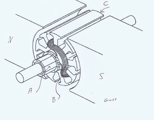 |
Coreless Servo Motor
The coreless motor is completely different from the conventional servomotor as shown in the below sketch. The components are as follows: 1 is the brushes, 2 is the commutator, 3 is the rotating coil, 4 is the magnet, 5 is the housing, 6 is the flange or end bell, 7 is the pinion gear.
 I hope this article has helped you understand a little more about the coreless motor and how it is built.
|
Electrical Connections
By James Goss
I am sure you are aware that a lot of crashes are due to problems with the battery system that provides electrical power to your plane. Most in flight batteries will be a 4.8-volt supply at any number of ampacity ratings. Some modelers will use a six-volt pack to obtain more torque and speed from their servos, but by and large most will be 4.8-volt systems. The 6-volt systems will give your servos a 20% increase in torque. If you measure your 4.8-volt pack you will probably measure a voltage greater than 4.8-volts such as 5.2 or greater. This is their surface charge and will be reduced to 4.8-volts if a heavy load is connected across their terminals. Your voltmeter only places about a 200-milliamp load on the battery, and this is only if you have an expanded voltmeter with an internal load resistor built in. A 4.8-volt battery pack has four cells connected in series, each cell is rated at 1.2-volts. So here is a source of problems that may occur if a bad connection develops internal to the battery pack. This article deals with the number of connections that exists between your battery and the receiver that the battery supplies power for. Before you read on any further, try to determine how many electrical connections exist between the positive terminal of the battery and the servos that the battery drives for a typical installation.
In another article of mine entitled Redundant Systems (it may not have been published yet) I discussed how important the wiring between the battery and receiver is and some of the ways to make it more reliable. As you can see from trying to count the number of connections above, there is quite a few and any one of them can bring your plane down. To start with, a 4.8-volt battery has 8 connections and a 6-volt has 10 connections. These connections are internal to the battery and we have no control of them unless you make your own battery packs. If you make your own packs you will use standard solder or maybe silver solder to make the connections. This is ok but it does expose the cells to high heat. Most manufactures will use resistance soldering (spot welding) to make the connections. This is reliable and with the jumper straps it is easy to place the cells in a very tight pack. Most modelers will use pre-built battery packs so we will not count those connections.
Leaving the positive terminal of the battery we will normally find a switch. The switch will have a plug on it so we can plug the battery in. Both the positive and negative side of the battery is switched so we count two connections for the battery leads and two at the switch input connector for a total of four connections. Contact between the pins in the plug will create two more connections for a total of six. The switch uses two sets of contacts so this requires four more connections for the wire soldering to the switch terminals and two for the contacts themselves for a total of twelve at this time. (I have always said that it would be a safer system if we only switched one side of the battery, the negative or positive side, and parallel the two sets of contacts in the switch for a redundant switch system. That way if one set of contacts became open the other set would still deliver voltage to the receiver.) The switch has an output connector for connecting to the receiver, and we now have a total of fourteen connections. We need to add two more for the pin connections between the plug and receiver, now we have sixteen. The receiver bus has male connections for accepting the battery; this is two more for a total of eighteen. The receiver bus also has male terminals for its output to the servos; this brings the total to twenty. The servo has two connections in its plug so we now have a total of twenty-two connections plus two for the pin connections, or twenty-four connections in our battery loop. How many did you count?
If you count the internal connections of the battery there are thirty-two connections in the total battery loop that can fail us and bring our beloved planes to the ground. Who would have thought that there would be thirty-two electrical connections in this little battery loop? If you count the internal connections of each cell (where the electrolyte connects to the case of the cell) the total comes to forty connections. Since we have no control of the internal battery cells, other that buying good name brand batteries, we will only count twenty-four connections.
With twenty-four connections it is easy to understand why voltage drop may occur in our flight systems. Remember that each connection will add resistance to the current flow and a tiny voltage drop will develop across each resistance. This battery loop forms a series circuit and in a series circuit all the individual voltage drops will add up to the source voltage. Ideally when the switch is closed all the battery's voltage will be applied to the servomotor. But due to voltage drop on the conductors and connectors a portion of the voltage will be lost. Having a grand total of forty tiny voltage drops may result in reduced voltage at the servo. The power that a servo develops varies with the square of the voltage, so a little voltage drop will produce much less torque by the servo. If you are controlling large surfaces on giant scale or on fun fly planes that have bookshelves for ailerons, you may want to check for voltage drop.
If we had a way to check for voltage drop at the servo while the servo was under full load, we would know for sure if the servo was developing all the power it was designed for. To do this we would need a storage voltmeter that could store the lowest voltage that it measured during a given time. I don't think you will find a device such as this at Radio Shack, but they would have the parts to build it. In the November 2001 edition of RC Modeler magazine on page 42, you will find the exact device I am talking about. It is called an E-Trap and is designed to measure the lowest safe voltage that your servo receives. If you set the E-Trap for 4-volts as a reference, and the actual voltage at the servo drops to 4-volts, the E-Trap will turn on a led and let you know the voltage was indeed too low at the servo. This would be a great tool to have on your workbench.
You may wonder why you can't use a digital voltmeter to do the same thing. A digital voltmeter would not lock in because it takes time for them to settle down and give a fixed reading; they just hunt around for a while. The load on a servo is constantly changing while in operation. If you would like to check the torque of a servo on your workbench it is easy to do. Anchor your servo in position and connect to the receiver with a wye connector. Connect your voltmeter to the other wye connector. Connect a spring scale calibrated in ounces to the arm and pull the spring for 40 ounces. If the servo is rated for 44 ounces of torque it should move the scale. Remember the further you get from the shaft of the servo, the less torque the servo will develop if it is operating another horn such as a bell crank. So it would be better to connect the servo arm by a push rod to a bell crank that has the same length arm and the spring scale to the other arm of the bell crank. If you can maintain constant torque on the servo you may get a stable enough reading on your voltmeter to read voltage drop, but I doubt it. The E-Trap would be ideal for this test.
|
Weeping Will Improve Your Covering Job
By James Goss
I have seen the time when I wanted to set down and cry after I covered some planes, but this article is not dealing with that type of weeping. This type of weeping deals with venting certain areas of your plane so it can breathe as the ambient temperature changes. The first area that comes to mind is the canopy. If your canopy is completely sealed, as when you glue it in place, you need to drill a tiny hole in an out of the way place so it can breathe. This will help prevent it from fogging in cold weather.
The next place to install weeping holes is in the tail section and ailerons if they are stick framed. Stick framing is popular because it is light in weight and resists warping as compared to solid sheets of balsa. When you are covering these sections and begin to install the film, you always cover the bottom side first and then the topside. As you start the topside you will notice as you place the iron on the covering it starts to balloon up because of the hot air expanding. This ballooning will never allow the covering to seat, as it should. When the heated air cools it will allow the covering to go back down, but it will not be as tight as it should. It will wrinkle in the future for sure and you will heat it up again but it will still balloon, this can go on for years.
The answer to this problem of ballooning is to drill tiny weep holes in all the framed sections connecting them together. Then drill one final hole in the trailing edge of the stabs or leading edge of the elevator, rudder, or ailerons. Keep this hole open as you cover, some modelers close it at the end of the job to hide it from sight, This is where they go wrong, do not cover this weep hole, leave it open because the sun will do the same thing as the heating iron. Leaving it open will allow your covering job to breathe as the temperature changes in the future. I have found weeping to really work wonders with my covering jobs.
|
Pressure Testing Your Fuel Tank
By James Goss
During the last year or so I have come across an important procedure that I think we all should do on a regular schedule as part of our airplane maintenance. Over the years when I installed a fuel tank in a model I would assemble it and try to put a little pressure in it by blowing into it to see if it would hold the pressure. This method seemed to work ok at the time but there is a much better way to make sure your fuel tank is airtight and will not leak. The reason I am so interested in the subject of leaking fuel tanks is because of the type flying I am doing at this time. I like to hover close to the ground and to do this the engine must not fail. If you are using a pumped engine such as the os .91 a small leak in the tank will not hurt anything because this type engine does not depend on feedback pressure from the muffler. Any other engine that requires tank pressure will normally quit running if the tank looses pressure. For most 2-stroke engines the tank pressure is between .2 and 1.5 psi from idle to max rpm. The 1.5-psi is not much to start with, so if you loose any of the tank pressure at all the engine will drop in rpm, especially if you are in a hover with the nose pointed straight up.
The best way to check your tank is to pressurize it with a known pressure amount. I use a small hand pump that can put positive pressure into the tank or a vacuum as well. I prefer the positive pressure because this is what the tank is exposed to in actual use. A vacuum may tend to pull a crack together whereas positive pressure will tend to open the crack to some degree. I also use a small pressure gauge that reads from 0 to 30 pounds of pressure. When I assemble the tank for the first time I always use compressed air to clean out the tank. In the past I have found several tanks that had plastic shavings in them from their molds. These cuttings ended up in my carburetor and had engine failure. (Where was that in-line filter?) After the tank is assembled I connect the pump and gauge set and pump 5 pounds of pressure into the tank. I let the tank set for about ten minutes and allow the pressure to exhaust; I then repeat the process again. If I really want to test it I leave the charged tank over night, it will not leak down any if the tank is sealed. It is not good enough to pressurize the tank and just listen for the air to escape; you need a pressure gauge so you can see the slightest amount of pressure change. The next best thing would be to charge the tank and put it under water so you can see bubbles if it is leaking. This works ok if the tank is not inside your plane, but you do not know how much pressure the tank has in it. Knowing the exact amount of pressure in your tank is the key to really knowing what is going on. Using the pressure gauge will allow you to check the tank any time and anywhere, even at the field.
So remember that tanks having pressure leaks can cause a lot of problems for your plane and they can be hard to pinpoint without a way of testing such as this. After I set up my fuel tank pressure tester I went back and checked several tanks that I had used in the past with engines that had troubles. To my surprise I found four tanks that would not hold 5-psi of pressure for a period of one minute. From now on if I have engine trouble I will let this be the first check on my list. It is a simple test even at the field. Just get access to your fuel lines and connect the pump and pressure gauge. Set the pressure to 5 pounds and see if it holds for a few minutes. Most leaks I found were around the stopper. If you have access to your tank while it is charged to 5 lbs you can also squeeze the tank. This will surge the pressure up and down and a peak pressure of about 6 pounds really makes for a good test.
You might think that if the fuel tank only receives a maximum of 1.5 psi on a 2-stroke, even if the tank had a leak at 5-psi, it may not leak at 1.5-psi. Chances are that if it does leak at any pressure you are going to have trouble in the future. The idea of this test is to prevent a major engine failure before it happens by testing on a regular basis. If you charge the tank to 5 psi and after 5 minutes it has leaked down to 4.8 psi, even this tiny amount tells you that something is wrong and an inquire is in order.
If you are using a YS engine you had better perform this test for sure. This type engine places about 6 pounds of pressure in the tank. I have not measured the tank pressure that a YS engine develops, but I was told that it was in this range. The next time I run my YS 120 FZ engine I will test it and let you know the precise amount. I know for a fact that a great planes fuel tank will not withstand the feedback pressure of my 1.20 engine. While hovering about 30 feet off the ground the 12-ounce great planes tank exploded from excess pressure and instigated a crash. You may remember about two years back Great Planes had a massive fuel tank call back. Their tanks would always split down the front seam after only one flight. I had several to do that and several of my friends also had that to happen. So just because a tank is new doesn't mean it is ok. Always check your new tanks under controlled conditions before it is installed into your expensive plane. Your engine is no better than its fuel tank. If you are going to spend two, three, or four hundred dollars for an engine, spend a few bucks for an outfit to pressure check the fuel tank. This time will be well spent and worth the effort. Also check the system every few weeks during flying season because leaks can occur at any time and it only takes three minutes of your time. By doing it on a regular basis a fault will show up as a tiny leak before it becomes a major problem.
Here is a handy tip to help insure against pressure leaks on your tanks, especially if the tank is installed out of site. Even if the lines coming out of your fuel tank have barbed connectors or if they are straight brass pipe, use this method. Place small nylon tie wraps around each tank line for added protection against leaks. This is really needed on YS engines, but will improve any system. These nylon tie wraps will work better that the fuel line spring clamps such as Great Planes and Dubro offers.
Update
Since I started this article I have now had an opportunity to check my YS-120 4-stroke to see what the maximum pressure is that the tank must withstand. I did the check last Wednesday (November 28, 2001) at the Eastaboga field. I first checked the pressure that the engine produced without it running. To do this I connected the pressure gauge on the engine side of the check valve. Each turn of the prop generated a peak pressure pulse of 2-psi. With the gauge connected on the tank side of the check valve I started to run the engine. It builds up pressure fast and in about 15 seconds with the engine at max rpm the gauge showed almost 8 pounds of pressure on the tank. This is more than I was expecting and now I am really concerned about my fuel line connections being able to handle this pressure. The slightest nick or cut on a fuel line can induce a leak in the system. This high pressure is not only acting on the fuel tank, but also on all your fuel lines and fittings that you might be using. So to pressure test this type engine you would need to charge the tank to at least 10-psi minimum and maybe 12 pounds maximum. I wish all fuel tanks came with barbed connectors because straight brass pipe offers little resistance to the fuel line coming off. I am searching for 1/8 inch barbed brass pipe at this time and if I find any I will let you know.
|
Here is Buddy and Bomber. Bomber is the short one!!!
 |
 Buddy is getting a feature article ready about sky diving.
|
Update On Building a 1/2 Scale Cap 232
By James Goss
Well here it is December already and I am back on track with the Cap 232. I had gotten off on several other projects during the last few months and let the Cap sit idle. This time I started with the tail sections and got them sheeted with 1/16-inch balsa. The horizontal stabs are very thick but relative small in size. The elevators are huge and occupy most of the area for the tail section. Same design for the vertical stab, small stab with huge rudder. The rudder servo will be mounted in the vertical stab and the elevator servo will be installed in the horizontal stab. The horizontal stab is in two pieces and will be a plug-in design with a 7/8-inch round aluminum spar. Getting the holes drilled for the aluminum spar turned out to be quite a chore. The pipe must run true and level as it goes through the tail section so the horizontal stab will be parallel to the wings. With this accomplished I began construction of the vertical stab and rudder. I had purchased all the balsa and ply for this project and had it put aside until I needed it. Scratch building several planes in the mean time I dipped into my earmarked supply of balsa and now I was out of 1/16-inch sheeting. Placed a call to Balsa USA and got some on the way. Not being able to finish the rudder I decided to start the wings.
Let me say first that these wings are really big, I mean huge! Each wing panel is in four separate sections with a large spruce spar running the length of the wing. I am using thinned epoxy to sheet the wings with 3/32 balsa. I thin the epoxy with a 50/50 mix of epoxy and alcohol. This is the first time that 48 inch balsa was not long enough to sheet a wing panel. Each panel is 67 inches long and the fuselage is 13 inches wide, this adds up to the 147-inch wingspan. I have just finished cutting the slots in the fuselage for the wing spars to enter. They are 4 5/8-inch high and 3/8 wide. The wooden spars will go through these slots and overlap each other inside the fuselage. A wooden box built from ¼-inch plywood and enforced with carbon fiber will house the spars. This is where I am in construction at this time.
|
New Giant scale Plane
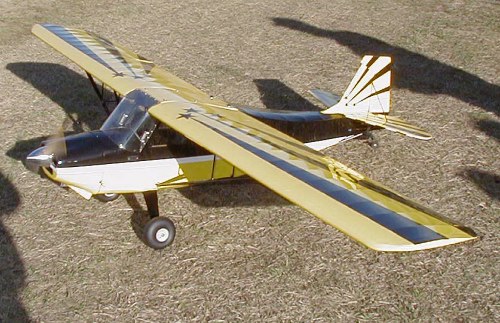 Commemts by Dr. Vic
Kit: Bud Nosen 25% Citabria
WS: 106 inches
Weight: 17 lbs (dry)
Fuel cap: 17 oz
Engine: RCS140 gas (weighs less than 2 lbs including the ignition system)
Radio: Hitec Supreme 8 ch on regulated 6 volts
Servos: (4) Hitec HS-645MG 133 oz. in. torque at 6 volts
(1) Hitec HS-81 micro servo (throttle)
Ignition: Electronic auto-advance/auto-retard (4.8V) with opto-isolated
radio-operated kill switch in series with a heavy-duty DCS manual switch.
Extras: Two on-board voltage monitors for the 4.8V and 6V batteries (1400
mah and 1800 mah respectively). Custom instrument
panel from drawings submitted to TnT Landing Gear. Detailed interior with
foam-cushioned, upholstered pilot's seat. Will eventually order a pilot
who will appreciate the comforts provided.
Impressions: Takes off like a Cub (requires diligence on the rudder and
you have to get the tail flying and hold the nose low until it attains
flying speed), flies great, easy to land. So far, I am very satisfied with
this airplane. I will be flying this one at Munford on Saturday mornings.
I won't fly it at Eastaboga until I get more familiar with it.
Vic C.
|
This is my new Flubber-Hoover Plane. It was built to flat spin like no other plane I have had. It will flat spin in an upright and inverted position and will stay flat all the way down. It has a 41 inch span and uses an OS- 91 four stroke with pump.
 |